Page 1 of 1
Electrical scheme of the output pin
Posted: Thu Apr 02, 2015 3:36 pm
by Jan Lichtenbelt
Hi,
1) Where can I find the electrical schem of the output pin, TTL or Schmitt Trigger? Espeacillay for the PIC16F876 or equivalent.
2) Is there a typical load resitance of 230 Ohm?
with kind reagrds
Jan Lichtenbelt
Re: Electrical scheme of the output pin
Posted: Thu Apr 02, 2015 4:56 pm
by Benj
Hi Jan,
In the microchip datasheets there is a section named electrical characteristics which should detail everything you need to know. If you need a good PDF viewer then I can highly recommend PDF-XChange, I've used it for years without a single issue and it's literally miles better than Adobe or the web browser defaults.
We add 220 Ohm to the signals on our E-blocks to ensure that nothing is damaged if a high output pin is shorted to a low output pin.
Re: Electrical scheme of the output pin
Posted: Fri Apr 03, 2015 12:55 pm
by Jan Lichtenbelt
Dear Ben,
Thanks for your reaction. I do not found in the specifications. But I found it in Wikipedia under TTL.
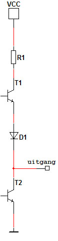
- Totem-pole_uitgang.jpg (21.27 KiB) Viewed 9413 times
With 2 outputs, one high and one low, connected external with a 330 Ohm resistance I found R1 to be about 72 Ohm and the voltage Vce over the T1 to be 2V with a current of 12 mA. (PIC16F876A used)
I never realised that ouput high will not be 5V and output low will not be 0V. In the case above they will be respectively 4 and 0.2 Volt.
With kind regards
Jan Lichtenbelt
Re: Electrical scheme of the output pin
Posted: Tue Apr 07, 2015 11:24 am
by Benj
Hi Jan,
No you should get pretty much 5V for an output high and 0V for an output low, depending on how much current is being drawn.
This is the circuitry of an I/O pin in the 16F876A.

- PinDiag.jpg (36.36 KiB) Viewed 9390 times
FETs are used as they don't have the inherent voltage drops that transistors have. Instead they have a resistance but this will be very low, probably only a fraction of an Ohm.