24HJ64GP202 – Clock settings – Internal oscillator

For questions and comments on programming in general. And for any items that don't fit into the forums below.

Moderators: Benj, Mods

Post Reply
viki2000
Posts: 190
Joined: Mon Jul 07, 2014 9:38 am
Has thanked: 30 times
Been thanked: 77 times
Contact:

24HJ64GP202 – Clock settings – Internal oscillator

Post by viki2000 »

I use FC6.
I just make a simple 10ms on and 10ms off test with 1 pin and I get 17.2ms in reality.
I want to set the internal clock to 80MHz using PLL and I need clock out function.
I have the 28 pin SPDIP package, so that should be pin 10, RA3 where is OSC2/CLKO, but I see no signal there.
I have an error somewhere.
Do you have any suggestions to track it down?

Image

I have tried also FC7 with updates from here:
viewtopic.php?f=63&t=18760&p=80726#p80726
I get Clock Out, but only 23MHz and the on/off is still 17ms instead of 10ms.
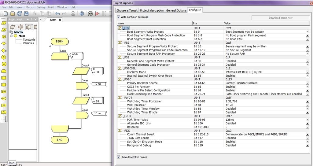
It is something wrong with the clock settings.
Here is the code:
PIC24HJ64GP202_clock_test.fcfx
(7.11 KiB) Downloaded 282 times

viki2000
Posts: 190
Joined: Mon Jul 07, 2014 9:38 am
Has thanked: 30 times
Been thanked: 77 times
Contact:

Re: 24HJ64GP202 – Clock settings – Internal oscillator

Post by viki2000 »

In mean time the problem is solved by specifying manual the clock settings according with datasheet formula (N1, N2, M).
N1=3 (PLLPRE, Input/3) would mean FCR/3=7.37MHz/3=2.456MHz, which is in the required range 0.8MHz-8MHz
Then M=63 (PLLDIV=0x3F) then we get 2,456MHz*63=154.77MHz for VCO, which is in the required range 100MHz-200MHz
N2=2 (PLLPOST, Output/2) and we get 154.77Mhz/2=77.385MHz.
Actually I had to add this setting in the beginning of the flowchart as C code by setting the corresponding registers for N1, N2 and M:

Code: Select all

OSCCON=0x1120;
CLKDIV=0x0001;
PLLFBD=0x003F;
OSCTUN=0x0000;
In fact works also if I add only CLKDIV=0x0001; and PLLFBD=0x003F; , but is "safer" to specify clear all 4 registers.

Here is the working code, which provides 10ms on and 10ms off at pin RB8 and 40MHz at OSC2 pin:
PIC24HJ64GP202_clock_test_solved.fcfx
(7.15 KiB) Downloaded 280 times

viki2000
Posts: 190
Joined: Mon Jul 07, 2014 9:38 am
Has thanked: 30 times
Been thanked: 77 times
Contact:

Re: 24HJ64GP202 – Clock settings – Internal oscillator

Post by viki2000 »

The PLLFBD above value is not quite right.

According with PIC24H Oscillator manual page 22, next settings are better to get 80Mhz:
N1=2, N2=2, M=43 as value which corresponds to 41 as setting, which is 0x29 in hex.
Page 126 datasheet (M is PLLDIV): http://ww1.microchip.com/downloads/en/D ... 70293G.pdf
OSCCON=0x1120;
CLKDIV=0x0000;
PLLFBD=0x0029;
OSCTUN=0x0000;
http://ww1.microchip.com/downloads/en/D ... 70227B.pdf
http://ww1.microchip.com/downloads/en/D ... 70308B.pdf

Post Reply