Creating the 6 DoF Platform – Pt2
 In this follow-up to part one (rapid prototyping) article we will discuss how we created an Android based application to run on a tablet which transmitted XY rotation data out over Bluetooth to our Arduino. We will also discuss the Bluetooth module we attached to our Arduino and how this was programmed in Flowcode. Finally, we will discuss how we created the maze structure for the top of the platform using 3D design Software and a laser cutter.
In our first article we demonstrated how we were able to quickly develop a crude rapid prototype of a 6DoF Platform in preparation for the Electronica Show. In that article we discussed how we used potentiometers to mimic XY rotation, which would later be achieved from the accelerometer within a tablet device This prototype gave us confidence to continue with the prototype, so we find ourselves here in article 2.
The Android App!
The android app was created using the Android SDK and Eclipse IDE. The code started life as the BluetoothChat example which is part of the main Android examples pack that Google provides to supplement the SDK. We downloaded the BluetoothChat app from Google Play and used to first test the embedded hardware functionality by sending manual characters and using an LCD to display the incoming characters. This worked really well so we then checked that the source code compiled and worked correctly on the Android device. This proved to be problematic as the latest Android SDK has some changes which caused the example to have compilation problems. Thankfully all the problems were well documented and we were able to change the code enough so that the app compiled and ran on the Android device.
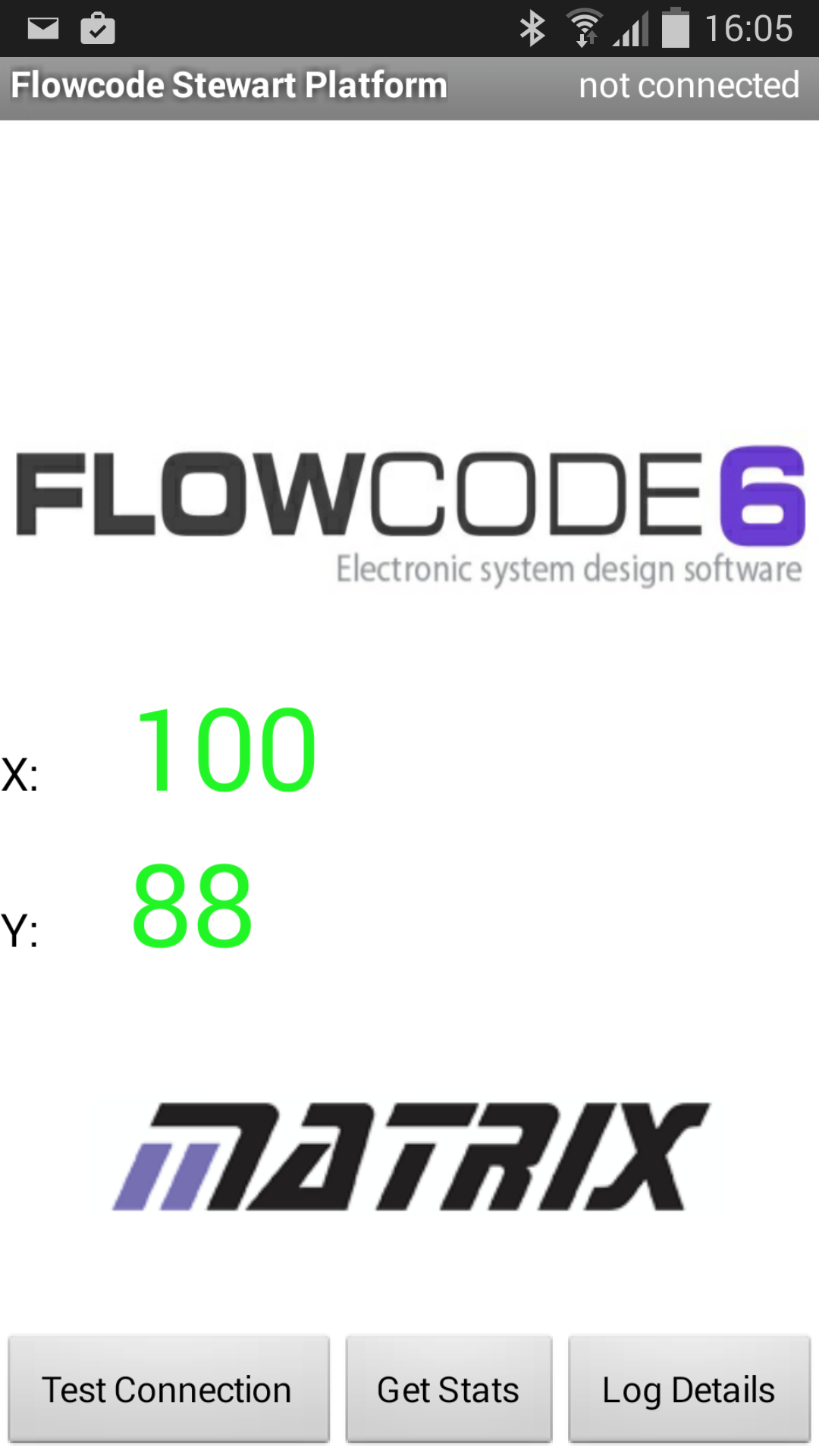
After following a few Android tutorials we felt confident to edit the example app enough to change the GUI and add buttons to do specific jobs. The Jump button is an example of this where we send a specific ASCII character ‘j’ wherever the button is pressed. The Arduino would then respond to this character ‘j’ differently to how it responds to the XY rotation data. We then looked up the Google Android example code to access the accelerometer. This proved to be very easy to add into the app with just a few lines of code. There is a function which is automatically fired whenever the sensor value changes and this function simply calls similar code to the Jump button. This time we send the character ‘x’ followed by the scaled 0-255 byte value of x and the same for the Y axis. A value of 128 represents the mid-point when the android device is completely level. The only addition to this to finish things off was that we added a very simple low pass filter to the function to get rid of some troublesome vibration and oscillations in the raw accelerometer data.
A screenshot of version 1 of the app we created is seen below;
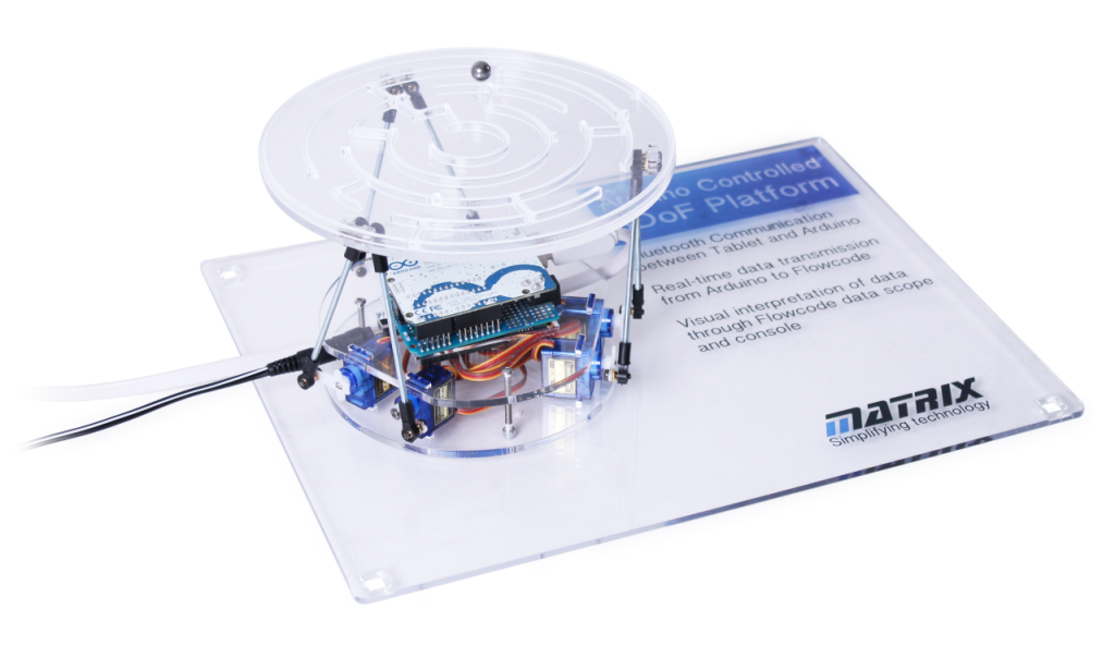
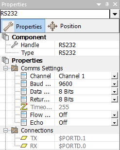
Next we had to add a Bluetooth module to our hardware to allow us to receive the data from the tablet. The Bluetooth module of choice was a HC-06, a great little module that connects to the Arduino over Serial connection. Luckily this is nice and simple in Flowcode using the RS232 component. We configured the RS232 component in Flowcode to match that of the UART on the Arduino; Digital 0 and Digital 1. You may also notice that we changed to the Arduino Uno at this stage of development. The reason was that we wanted to place the hardware inside the 6DoF platform, and using the smaller Arduino Uno made this easier.
In terms of hardware connections, we purchased an Arduino Proto Shield for all our additional hardware to make our connections. In the image below you can see the Bluetooth module connected to the Arduino via a pair of black cables. We also attached 6 servo connectors to allow the servos to be controlled from the same shield (Digital 8-13). The final part of the board is a DC power connector, allowing the separate power supply required for driving the servo motors. Note that despite the external power supply the servo control signals still come from the Arduino Uno.

Within Flowcode we needed to create code for the Arduino that received Bluetooth data. We configured the UART0 interrupt, which automatically fires a section of code each time data is presented on the UART of the Arduino. In this example, it means that we do not need to continually poll the UART for received Bluetooth data. Instead the Arduino can concentrate on other tasks and only receive data when there is an incoming packet. Below we can see that whenever the UART interrupt fires we first receive the data and save it to a local variable named ‘.RxChar’. We then send that data back out over the UART so that we can receive the data for our real-time simulation (next article). Finally we save the data received into a circular buffer, another handy Flowcode component.

All received data was saved to allow us to calculate where the platform was and where it should be. We saved data in a circular buffer with a chosen size of 128 elements. In our 6DoF flowchart we continually check the contents of the buffer. If there is information in the latest index we then proceed to use inverse kinematics to calculate where the current position is, and how the servo motors will need to rotate in order to move to the desired position.
One final discussion relating to the configuration of the Bluetooth module was to send AT Commands to configure it before we begin receiving data. We do this again through sending serial commands. During the initialisation process we call a macro BTCommand. In this macro we send a string of text over serial, which configures the Bluetooth module. The command we sent changed the name of the Bluetooth module to ‘PLATFORM’ as can be seen below. During the initialisation procedure we also initialised RS232 comms, initialised our variables our motors. With most embedded systems you go through an initialisation process to get a good clean starting point to begin your program. Initialising the motors in this example reset them all to point 0, to give a level platform. The next initialisation command flushes the buffer, which empties its contents and resets the index to zero. Finally, we enable the UART interrupt, and here we can see that when that interrupt fires it will call the macro ‘RxInt’.

Maze creation and laser cutter:
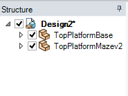
The final part of this blog article discusses the maze which sits on top of the platform. We created the maze using Design Spark Mechanical, a fantastic 3D drawing package which is available for free from RS/ DesignSpark. We knew the outer dimension we wanted for the maze so created a circle of this size. We then drew a 2D circular maze with only one path to the middle. We used the ‘Pull’ feature in DesignSpark Mechanical to extrude the maze shape upwards. The final maze was actually cut from two pieces of clear 3mm acrylic. The first was the flat base ‘TopPlatformBase’ with the mounting holes and the second was the maze outline itself ‘TopPlatformMazev2’.
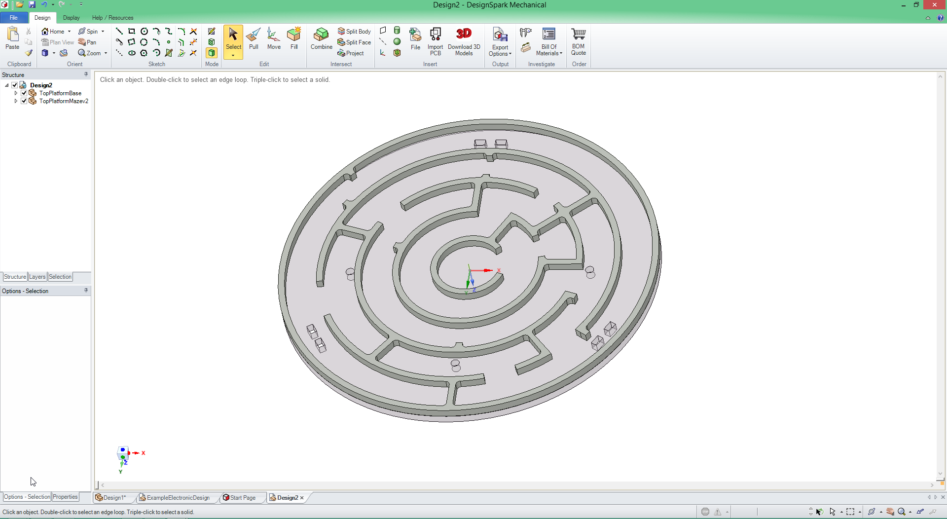
With both mazes designed we saved them as .DXF files, compatible with our laser cutter, and cut them out. We glued the two parts together to create the final maze. With the mounting holes we were able to mount the maze on top of the rods connecting the servo motors.
We’ve reached the end of our blog article for this week. Next time we will discuss the final few steps of creating the 6DoF platform and how well it fared at the Electronica Exhibition, along with converting it to use Microchip PIC based hardware.
6,685 total views, 1 views today


