Introducing the new Matrix TSL dual full bridge motor driver E-block
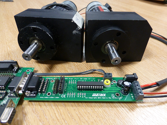
This new addition to the Matrix TSL E-blocks range is a motor driver board which uses the L6206 DMOS dual full bridge driver IC and is designed specifically for motor control applications, having isolated DMOS Power Transistors combined with CMOS and bipolar circuits and protection on a single device. Hence this motor driver E-block board allows the user to connect and independently drive two motors in full bridge (H bridge) configuration. Alternatively, the four terminals can be used as separate sink or source outputs.
The E-Blocks EB094 FET Motor Driver board will operate with both 3v and 5v logic systems, and with motor power supplies from 8 to 30 volts. Each full bridge driver can supply continuous current up to 2.8 amps. The board also provides internal motor flyback (freewheel) diodes, over current protection and thermal shutdown.
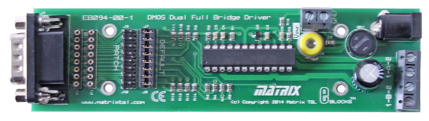
The motor driver outputs are provided on screw terminals, marked 1-A-2 for full bridge channel A and marked 1-B-2 for full bridge channel B.
Bridges A and B are independently enabled or disabled and their respective outputs 1 and 2 can either drive high and source current or drive low and sink current. Hence a motor can be driven forwards or reverse via this full bridge mode.

The diagram illustrates how the two outputs of each bridge can be driven, high, low or off, and hence drive the motor: forward, reverse, off (freewheel) or brake.
A particular feature of the new E-block motor driver board is the improved performance and efficiency over a conventional bipolar transistor bridge driver (such as the L298)
This is due to the reduced current path resistance of between 0.3 and 1.1 ohms, whereas the L298 exhibits a voltage drop between 1.8 and 3.2 volts. Hence, for example, with a power supply of 12 volts the L6206 DMOS driver provides an efficiency between 91-95% rather than the 73-85% of the L298, giving much improved power transfer .
This feature is additionally valuable in battery operated applications, where the increased power transfer efficiency translates into increased usage between battery charges.
The following shows a sample Flowcode flowchart for driving two motors for a simple two driven wheel application.
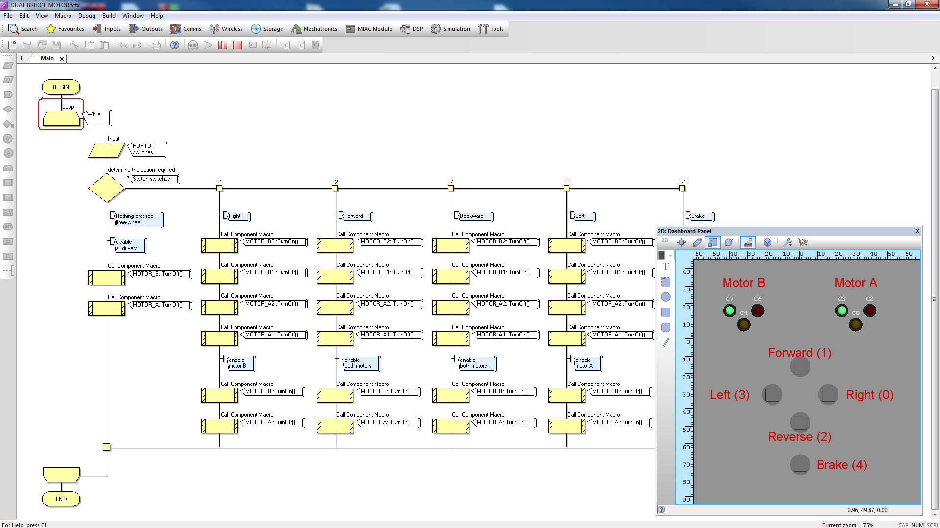
For more control over speed, the two motor bridge enable inputs would be driven with a PWM control output, rather than a static on/off signal.
8,035 total views, 2 views today


