Mechanical Engineers and Flowcode 7 – PWM using Flowcode
Introduction
We recently had a number of family members visit from Australia. I got talking to one of them who I hadn’t spoken to for a while and told him about the Flowcode IDE that I have been using a lot recently for in-the-home projects. He’s a more mechanical engineer by trade and asked if I had any way of using Flowcode to control a DC linear actuator via push buttons.
He had already tried to use switches and pots and found this quite challenging. I suggested he might want to look into using a microcontroller; a term many mechanical engineers become quite averse to. I agreed to put a prototype together for him during his visit and show him the outcomes.
The Actuator motor is controlled from 24 Volts DC. The control is from a 0-5 Volt input, supplied by a potentiometer. Turning the pot extends or retracts the actuator. In mechanical terms – this seemed very simple!
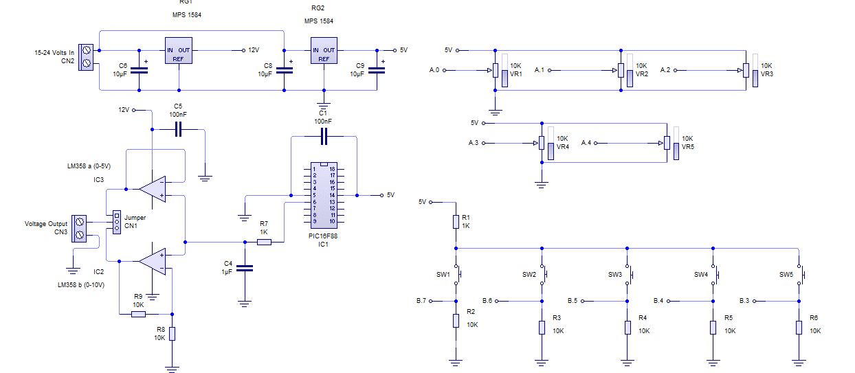
I had a PIC16f88 8bit micro to hand, including a PWM pin and various ADC’s, digital inputs and outputs.
So I used five ADC inputs for the “pot-presets” and five digital inputs for the momentary switches. One of the switches is tactile; mounted on a PCB and is used to set the default position for the actuator. On power up as this may not be at one extent.
The other four pots and switches are used as presets and can be set via the voltage on the pot wiper.
Using the PWM gave me 0-5v output; as PWM runs in the background on the PIC16f88 using timer 2.
I set up the duty cycle 0 -100% (0 = 0V to 255 = 5V in a Byte variable.)
Using Flowcode
Next, using Flowcode I set about creating a simple program.
> I set the internal oscillator to run at at 8MHz, and put in a simple amount of basic C code to action this (below):
osscon = 0x70;
> I created the Byte variables that I needed
pot_0 to pot_4 and sw_0 to sw_4
> Using one pot and one switch to set the default actuator position on power up.
Variable pot_4 equals the wiper Voltage of the pot 0-255 (0 = 0V to 255 =5V )
> Then making the PWM duty equal variable pot_4 (0-255)
> Pressing the tactile switch and adjusting the pot to set the default position of the actuator.
> Call a “component macro” for an input and assign variable sw_4.
> Then insert a decision “if sw_4 =1” when the switch is pressed the input goes High (1)
> Call a component Macro for the potentiometer and assign it the variable pot_4
> Call a component Macro for the PWM duty and assign it the same variable pot_4.
Once all of this is done, I was left with variable pot_4 equals the wiper voltage and the PWM duty equals pot_4 so the PWM duty is equal to the wiper voltage.
This outputs a PWM voltage, equal to pot wiper.
I added an RC network to the PWM pin B.0 as a low pass filter, which enabled the conversion of the PWM pulses back into an analog voltage.
Next I fed this into two op-amps, one as a voltage follower 0-5V. The other has a gain of two giving an option for 0-10V.
The purpose of using the op-amp was that it has a large input impedance and low output impedance as well as being capable of sinking 20mA to drive the input for the actuator. This left the other four switches and potentiometers to be used presets.
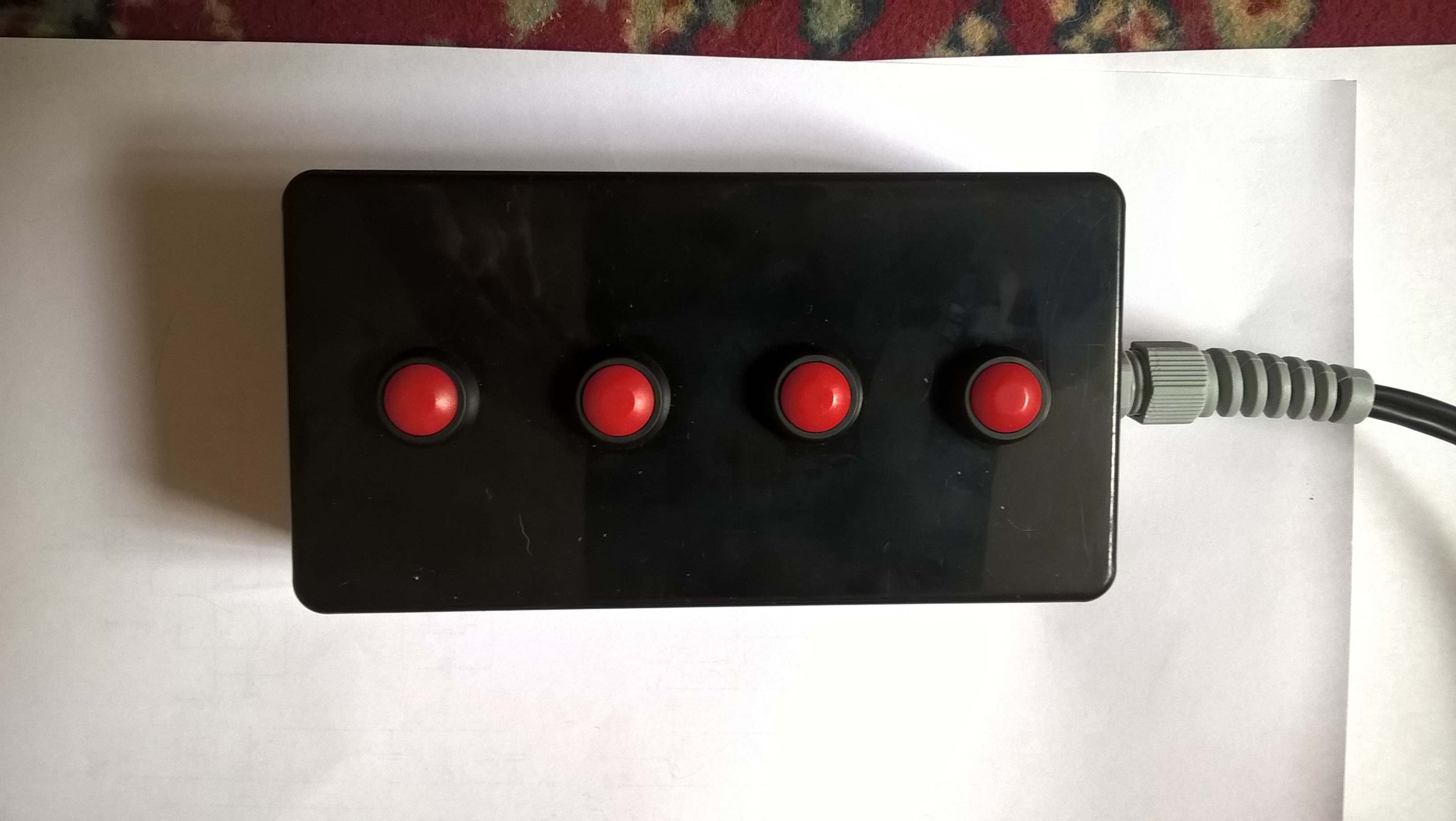
By pressing and holding one of the switches and changing the Voltage of the pot we can set the preset positions. The four momentary switches are mounted externally.


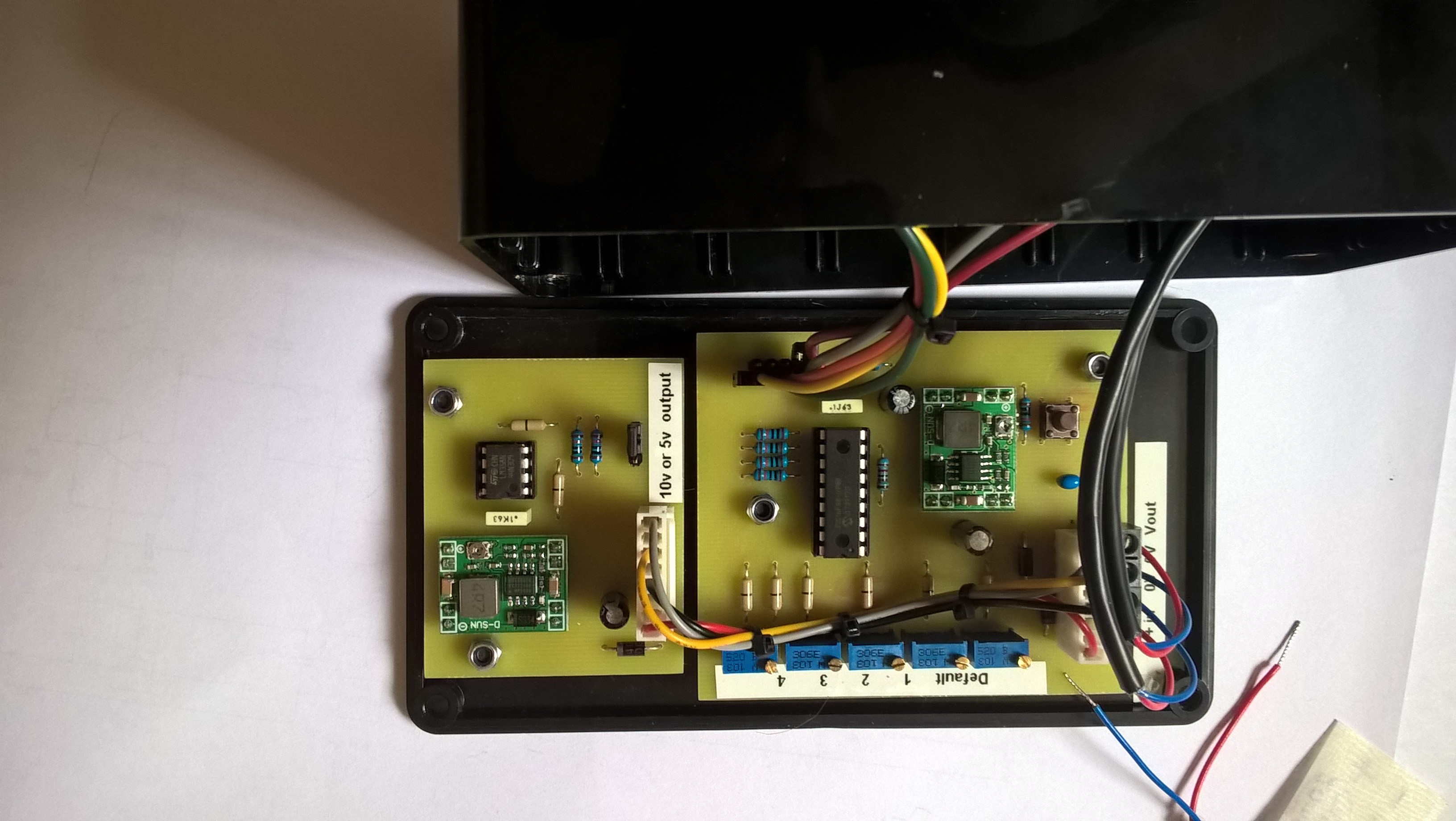
As you see from the picture above, the op-amp is on a separate board. This was an after-thought to cover my goal just in case the 0-10V is ever needed.
The short video below shows it powered up. Its shows 1 Volt on the multimeter this is where I have set the default power up pot. Once set it will never be adjusted again.
The external buttons are set roughly 1 Volt apart, and it is noticeable that the voltage never drops back to zero volts. This is done so the actuator never retracts to fully closed before the next preset is selected.
When my family member tries the switches and pots without the microcontroller, it would retract the actuator, as the voltage drops back to zero. You can see the final project hardware I created, below.
Click here: 4-button-pwm-v2 to download the Flowcode file for this project.
15,383 total views, 1 views today


Brilliant! This product is available through BAL Enterprises.
Good joke Bruce, Adam