MIAC PLC – Mini Hydro Generator
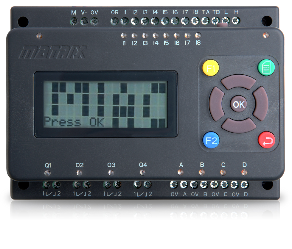 The MIAC is a very capable unit for controlling systems, creating test mechanisms and communication thanks to it’s USB and CAN connections. It is also a fraction of the price you would pay for a similar Siemens PLC and most importantly it is fully compatible with the Flowcode software.
The MIAC features a ruggedised PIC microcontroller brain allowing you to completely move away from typical outdated PLC ladder logic programming and towards Flowchart, C or Assembly based coding. Using the MIAC with Flowcode 6 allows you to achieve very advanced functionality in a very small time frame allowing you to do much more. The MIAC hardware can also be controlled directly from the Flowcode 6 environment using the built in MIAC USB Slave component allowing a SCADA type control environment.
A great example of the MIAC being used out in the field is in Sri Lanka where four MIAC untis have been networked together to control a mini hydro generator.
The scene
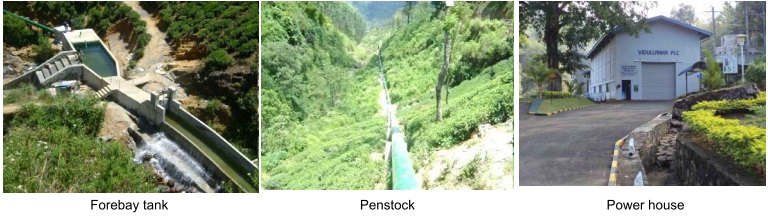
The graphic below shows the layout of a small valley in Sri Lanka. The river in the valley has been used for several years to provide power to a small hydro power station which supplies the national grid system. A part of the river flow is diverted through a channel along the side of the valley to a holding tank. The water from the tank is then fed to a turbine which generates electricity.

The following images give you a better idea of the scale of the project:
The problem
The generator installed in the power house is a 800kW three phase generator which has been running successfully for a number of years. However the control system for the generator is manual: whenever power is needed an operator has to use the manually operated hydraulic unit to feed water to the generator. This manual system is inaccurate, incurs delays in using the generator during start up, and means that power is only generated when the operator is present. It was felt that a modern electronic control system would allow more precise control of the generator, and would also allow the generator to provide electricity back into the national grid fully automatically increasing efficiency.

The top image on the left shows the turbine and generator. The top image on the right shows the turbine and generator and manually operated hydraulic control valve, next to a new electronically operated hydraulic control valve.
The solution
The solution is the control system , the schematic of which is shown below:
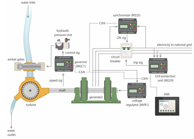
Water from the Penstock is fed into the turbine through a valve called a ’wicket gate. Because of the amount of water flowing through the valve, and the force needed to open and close it, hydraulics are used to open and shut the valve.
The first control section needed is a system that measures the speed of rotation of the Francis wheel turbine shaft which regulates the amount of flow into the turbine itself. In the old days this feedback loop was provided by a mechanical governor. Here a sensor picks up the rotational speed of the central generator shaft and feeds this into the first MIAC in the system. The MIAC controls the wicket gate aperture and the shaft speed so that the generator produces electricity at the correct frequency.
The second control section is used to set up the generator before connection to the national grid. The MIAC here measures the voltage produced from the generator and uses a Pulse Width Modulation output and a thyristor circuit to control the rotor voltage on the generator.
The third section is used to synchronise the system to the national grid before connection: if the grid and the generator are not at the same phase in the AC cycle at the time of connection then sparks will fly. The three phase output from the generator is voltage reduced and fed into this MIAC which controls the main circuit breaker connecting the generator to the grid.
The final section is used to protect the generator should a fault occur on the grid: for example if the grid voltage becomes too high or the frequency changes.
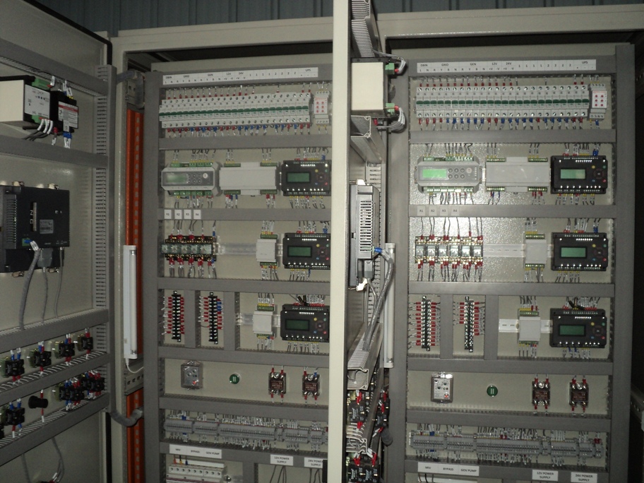
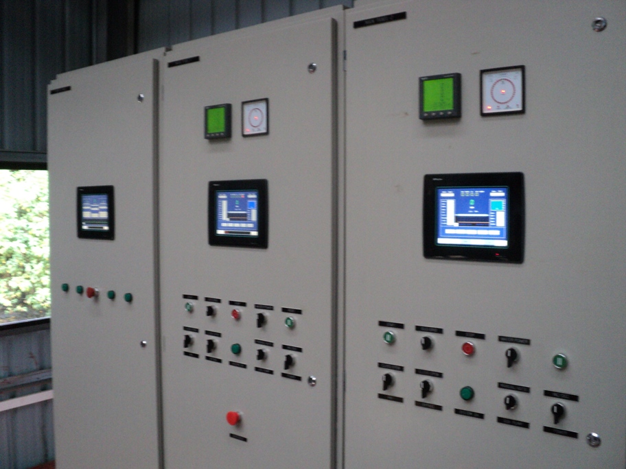
All four MIAC units are connected by the integral CAN bus. The MIAC units themselves are housed in metal cabinets by the side of the generator along with additional switchgear and circuitry for measurement. The programming of the units is performed in Flowcode.

Conclusion
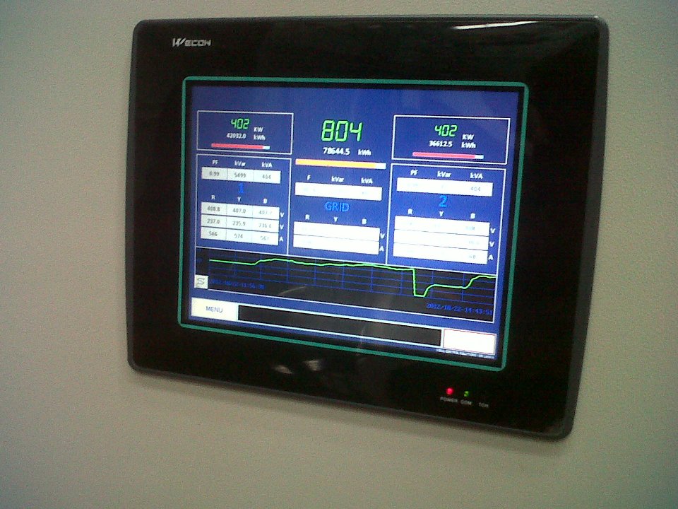
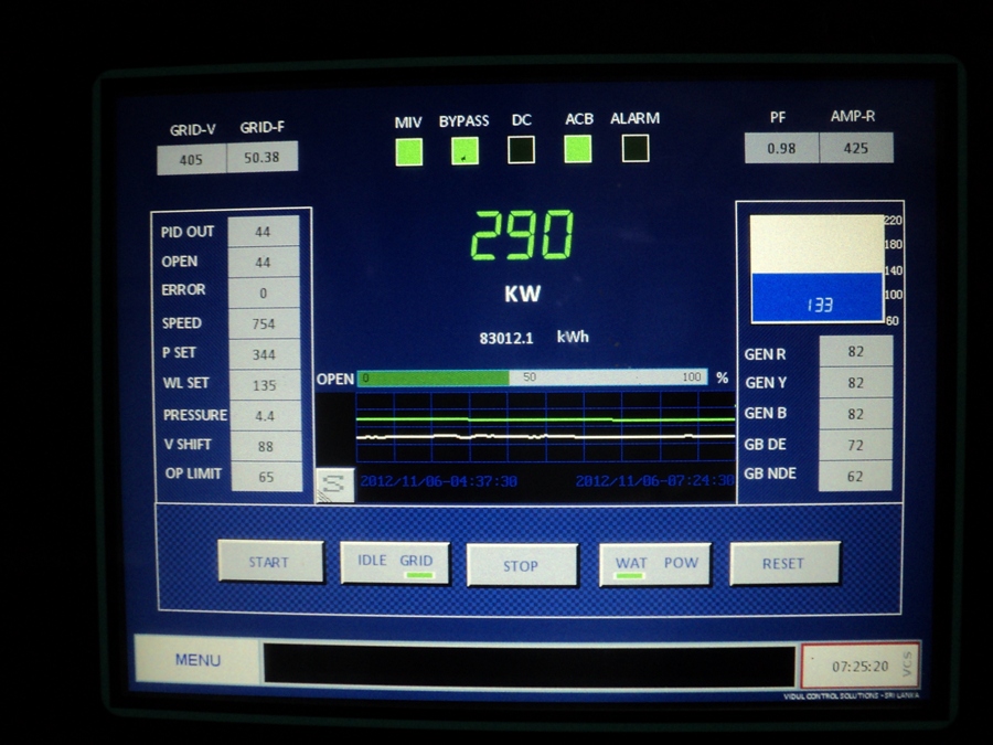
The system has been up and running since October 2011. A recent addition to the system has been a low cost Human Machine Interface module which interfaces to the MIAC units using CAN 2.0A which will allow for better control and monitoring of all parts of the unit.
Many thanks to Thushara Goonathilake and Vidulanka PLC for providing the material for this article.
Some simple Flowcode examples for the MIAC are provided here to aid with getting started with the MIAC hardware.
7,927 total views, 3 views today
Related Posts


About The Author
BenR
Embedded engineer with experience in Cybernetics (HMI), Robotics, Mechatronics, Control Systems and Communications using Microcontrollers and Microprocessors.