Exercise - Creating a Flowchart
The task is to produce a Flowcode flowchart that lights a lamp for ten seconds when a switch is pressed.
Although it may not be realistic to use a microcontroller in such a straight-forward application, it illustrates the technique of producing a Flowcode program.
The program itself may form part of a bigger program.
Contents
Formulate the sequence
The flowchart sequence will be:
- Check if the switch is pressed.
- If it isn't, go back to the beginning.
- If it is:
- switch on the lamp;
- wait for 10 seconds;
- switch off the lamp;
- go back to the beginning.
It takes such a short time for the microcontroller to carry this out, that we don't need to worry whether the switch latches on or not.
Set up the flowchart
- Open Flowcode.
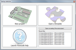
- On the Startup screen, click on 'New project'.
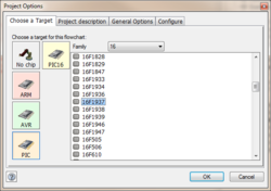
- The Project Options dialogue box opens.
- (Click on the link for a full explanation of all the options available.)
- Accept the default settings by clicking on 'OK'.
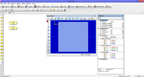
- An empty flowchart window opens, which may contain other items such as a System Panel, Dashboard Panel, Properties Panel etc.
- These can be revealed or hidden using the View menu.
- Set up the flowchart window so that you can see the System Panel and the Properties Panel.
- The flowchart window should resemble the one shown below (depending on the configuration.)
- The System Panel and Properties Panel can be moved by clicking and dragging the title bar at the top of each panel.
Set up the input
- More information about the icons used in this flowchart can be found in Icon Properties.
- Drag and drop a 'Loop' icon between the BEGIN and END icons.
- The 'Loop' icon will make the microcontroller repeatedly run through the program, (though the icon can be configured to limit the number of times this happens.)
- Inside the loop, drag and drop an 'Input' icon from the Icons toolbar.
- This will be configured later to read the state of the switch - to detect if the switch is being pressed.
Set up the switch
- Drag and drop a 'Decision' icon after the 'Input' icon.
- This icon will be used to make the program perform what is known as a conditional branch.
- When programmed, the current icons will be able to continually check if the switch is being pressed or not.
- In the next step we will be adding icons which will allow us to control what happens if the switch is pressed.
- Once the switch is pressed it will perform an the action or process and continue to check if it is being pressed again.
- If the switch is not pressed it will follow the 'No' branch and keep looping to continue to check if the switch has been pressed.
Set up the lamp
- Next we concentrate on the 'Yes' branch of the 'Decision' icon.
- Drag and drop an 'Output' icon in the 'Yes' branch.
- This icon is going to function as a trigger to turn the lamp on.
- Next we want the lamp to stay on for ten seconds and then turn off.
- Drag and drop a 'Delay' icon after the 'Output' icon.
- This is the icon which will allow us to delay the circuit for a specified period of time.
- The delay will last for 10 seconds, in this time the circuit will not be able to carry out any other function until the delay is complete.
- Finally we need to turn the lamp off, after the ten second delay.
- To do this we will need another 'Output' icon.
- Drag and drop a second 'Output' icon after the 'Delay' icon.
Your flowchart should now be set up to resemble the image to the right.
You should now save the flowchart as "Lamp1.fcf", and close Flowcode.
What next
The flowchart is now ready to be configured and programmed in order to operate electronic devices (components). The configuration of the flowchart is covered in the exercise Configuring Icons and Variables.


