Component: I2C Master (Comms: Interface)
| Author | Matrix Ltd. |
| Version | 1.4 (Release) |
| Category | Comms: Interface |
Contents
 I2C Master component
Generic Two Wire I2C Communications Interface
Detailed description
Overview
The I2C bus is a medium speed communications bus which is usually best suited for talking between devices situated on the same circuit board. Due to the high frequency digital nature of the bus care should be taken to keep tracks as short as possible and as far away as possible from other sources of noise. A typical I2C bus consists of two signals, data and clock. The I2C bus usually consists of a single master device and then one or more slave devices. The master device initiates all the communications and can only communicate with a single device on the bus at a time by sending a unique device address as the first byte.
Each I2C transaction consists of a start and a stop as well as one or more data bytes made up of 8 clock cycles allowing the 8-bits of each byte to be transferred. Each byte send is followed by an Ack (acknowledged) or a Nak (not acknowledged) from the receiving device.
Pull up resistors
The I2C bus usually requires pull up resistors in the range of 4.7K to 10K between the two I2C signals and VCC. Some I2C devices have the pull up resistors built in so as to avoid external components.
The pull up resistors can be useful when interfacing a 5V microcontroller to a 3V3 sensor as the pull up resistor can be connected to 3V3 to eliminate the need for voltage level shifting.
Start / Restart / Stop
The Start, Restart and Stop operations are each states which the bus can be put into using the I2C specification.
Generic Write Transaction
A generic write transaction to a memory device might look something like this:
Start
Send External Device Address Byte (Write mode)
Send Internal Address Byte
Send Data Byte
Stop
Generic Read Transaction
A generic read transaction to a memory device might look something like this:
Start
Send External Device Address Byte (Write mode)
Send Internal Address Byte
Restart
Send External Device Address Byte (Read mode)
Read Data Byte
Stop
Examples
More information on I2C can be found here,
Matrix Flowcode Blog: Simplified communications I2C and SPI
Generic I2C EEPROM
Example file demonstrating how to read and write bytes from a generic I2C EEPROM device.
![]() I2CEEPROM
I2CEEPROM
Simulated I2C devices
This example uses the I2C master component combined with the DS1307 injector to simulate an I2C communications bus between the target Microcontroller and the virtual DS1307 device.
![]() I2C DS1307 Example
The panel displays the current time from the DS1307 RAM which is populated to match the system time.
I2C DS1307 Example
The panel displays the current time from the DS1307 RAM which is populated to match the system time.
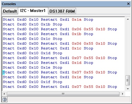
The I2C console shows the communications between the target microcontroller and simulated I2C device.
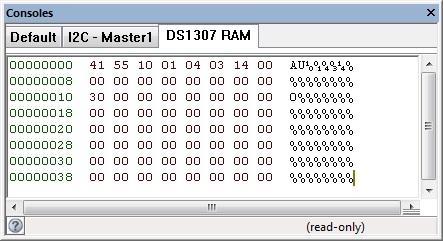
The DS1307 console shows the contents of RAM memory on the simulated I2C device.
Downloadable macro reference
ReceiveByte
Receives a byte from the I²C bus.
Parameters
- BYTE Last
- Used to signify the last byte when streaming incoming data. 0=Not last byte, 1=Last Byte
Return value
Restart
Outputs a restart condition onto the I²C bus.
Parameters
- This macro has no parameters
Return value
- This call does not return a value
Stop
Outputs a stop condition onto the I²C bus.
Parameters
- This macro has no parameters
Return value
- This call does not return a value
ReceiveByteTransaction
Function to perform a generic I2C read transaction. The 7-bit device ID is automatically shifted up by one bit to make room for the read/write bit. Returns the data from the location specified.
Parameters
- BYTE Device_ID
- 7-bit Device Address ID
- BYTE AddrH
- Internal Address High Byte
- BYTE AddrL
- Internal Address Low Byte
Return value
TransmitByte
Sends a byte on the I²C bus. Returns the acknowledge if any.
0 represents that data was acknowledged and 1 represents no acknowledge was detected.
Parameters
- BYTE Data
- Data byte to send on the I²C bus.
Return value
SendByteTransaction
Function to perform a generic I2C Write transaction. The 7-bit device ID is automatically shifted up by one bit to make room for the read/write bit.
Parameters
- BYTE Device_ID
- 7-bit Device Address ID
- BYTE AddrH
- Internal Address High Byte
- BYTE AddrL
- Internal Address Low Byte
- BYTE Data
- Data Byte
Return value
- This call does not return a value
Start
Outputs a start condition onto the I²C bus.
Parameters
- This macro has no parameters
Return value
- This call does not return a value
Initialise
Enables the I²C hardware and performs some initialization.
Should be called at the start of the program or at least before any of the other I²C functions are called.
Parameters
- This macro has no parameters
Return value
- This call does not return a value
Simulation macro reference
This component does not contain any simulation macros
Property reference
Channel
This property is of type Fixed list of ints and can be referenced with the variable name cal_i2c::CHANNEL.
Channel selection
Baud Select
This property is of type Fixed list of ints and can be referenced with the variable name cal_i2c::BAUD_LIST.
Baud rate option selector
Baud Rate
This property is of type Signed integer and can be referenced with the variable name cal_i2c::BAUD.
Baud rate to be used
Stop Delay
This property is of type True or false and can be referenced with the variable name cal_i2c::StopDel.
On older microcontroller devices there is a potential for the I2C hardware channel to lock up if there is not
a 10ms delay between an I2C stop event and the next I2C start event.
Most modern microcontrollers will not have a problem so this property can be disabled to speed up the
I2C communications.
Slew Rate Control
This property is of type Fixed list of ints and can be referenced with the variable name cal_i2c::SRC.
Slew Rate Control Enabled or Disabled
SMBus Inputs
This property is of type Fixed list of ints and can be referenced with the variable name cal_i2c::SMB.
When Enabled input logic thresholds are compliant with SMBus specification
SDA
This property is of type Single digital pin and can be referenced with the variable name cal_i2c::SDA.
Pin used for SDA (data signal)
SCL
This property is of type Single digital pin and can be referenced with the variable name cal_i2c::SCL.
Pin used for SCL (clock signal)
Label
This property is of type Line of text and can be referenced with the variable name label.
Label shown on the comms flasher on the simulation panel.
Scope Traces
This property is of type True or false and can be referenced with the variable name cal_i2c::ScopeTraces.
Selects if the scope traces are automatically generated or not
Console Data
This property is of type True or false and can be referenced with the variable name cal_i2c::ConsoleData.
Selects if the console data is automatically generated or not
Injector
This property is of type Fixed list of ints and can be referenced with the variable name cal_i2c::Injector.
No additional information


