Exercise - System Panel - Controlling Shapes
From Flowcode Help
The following assumes that you have added a single LED to the System Panel, as described in Exercise - System Panel - Adding Objects.
The aim of this exercise is to mount the LED on the car's instrument panel, and to control the viewpoint of the resulting component.
Contents
Open the LED flowchart
- Open the flowchart "System_Panel_Add_LED" which you created in Exercise - System Panel - Adding Objects.
- Check that the Panel Properties is displaying sizes as 'World size'.
- Move the LED into the top right-hand corner by clicking on the 'Move with the mouse' icon.
Add the instrument panel
- Click and drag a cylinder from the vertical toolbar onto the System Panel.
- Click on it to select it. You will see five properties listed on the Panel Properties,
- 'Shape', 'Color', 'Outline', 'Thickness' and 'Image'.
- The default 'Color' property is red (0x0000C0). Click on its value, and change the color to black (0x000000).
Change the shape of the instrument panel
- Click on the 'Scale with mouse' icon on the top, horizontal toolbar.
- Now, when you select the cylinder, eight drag handles appear around the edges.
- These allow you to reshape the cylinder by dragging on the appropriate handle.
- Drag on one of the horizontal handles until the width of the cylinder is 120mm.
- Drag on one of the vertical handles until the height is 60mm.
- On the Panel Properties, set the depth (De...) to 3mm.
- Centre the cylinder by setting its position coordinates to 'X'=0, 'Y'=0, 'Z'=0, on the Panel Properties.
- To make it look more realistic, locate the 'ADC dial' in the 'Inputs' toolbox. (This device can be used as an input device, but here it is being used as a decoration.)
- Click on the down-arrow to the left of the label, and select the 'Add to system panel' option.
- Click on the dial on the System Panel to select it and give it the following properties:
- 'Coordinates': X=0, Y=25, Z=5;
- 'World size': 'Wi...'=35, 'He...'=35, 'De...'=5;
- Now add two more dials in the same way.
- Give one 'Coordinates': X=-100, Y=0, Z=5, and 'World size': 'Wi...'=15, 'He...'=15, 'De...'=5.
- Give the other one 'Coordinates': X=100, Y=0, Z=5, and 'World size': 'Wi...'=15, 'He...'=15, 'De...'=5.
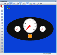
- The System Panel looks like the one opposite.
Add the LED to the instrument panel
- Now, move the LED back into position by selecting it and setting its position coordinates to 'X'=0, 'Y'=-60, 'Z'=0.
- Doing it in this order ensures that the LED appears on top of the instrument panel.
- Drag over both objects, and group them by clicking on the 'group' icon.
- At this point, save the flowchart as "System_Panel_Add_MountedLED".
Change the viewpoint
- Flowcode allows you to view these objects from different directions by changing the 'camera position' (viewpoint.)
- The first method uses the red, green and blue arrows at the top left hand corner of the System Panel.
- First, click on the arrowhead of the green arrow.
- This gives you a view of the objects from the 'green' direction.
- Now do the same with the head of the red arrow, to see them from the 'red' direction.
- Finally, clicking on the head of the blue arrow takes you back to the original view.
- There are three 'camera' controls that give finer control.
- The first is the 'pan' control that allows you to move the viewpoint to one side.
- To see this, click on the 'pan' control. Hold down the control (Ctrl) key, and click the mouse anywhere on the System Panel.
- As you move the cursor up and down or from side to side, the viewpoint moves accordingly.
- Notice that the coordinates of the objects do not change. The objects stay in the same place, but they are viewed from a different place.
- The second and third are 'camera rotation' controls.
- Click on the first of these. Hold down the control (Ctrl) key, and click the mouse anywhere on the System Panel.
- As you move the cursor, the objects seem to rotate, though, if you look at the 'Rotation' settings on the Panel Properties, you see that these settings do not change. Again, it is the viewpoint that is changing.
- Then, try the same with the other control.
Multiple views
- A powerful feature of Flowcode 6 is the ability to view the components from a number of different directions simultaneously.
- To see this:
- Click on the 'General options' icon.
- In 'Number of views:', click on the down-arrow and select "3".
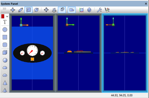
- By clicking on the appropriate arrowheads, set up each view as shown below.
- (Depending on the size and shape of the Systems Panel, the three views may be arranged vertically, instead of horizontally.
- Drag one edge of the Systems Panel sideways to see this effect. )
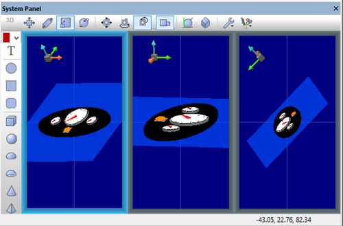
- You can adjust the viewpoint individually for each view, by operating the 'camera position' controls.
- An example of doing so is given below - notice the positions of the red, green and blue arrows in each:
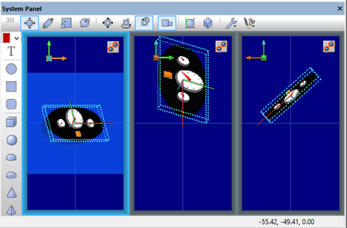
- Alternatively, you can make changes to the objects themselves, in which case all three views are affected at once.
- In the next image, the instrument panel has been rotated:
- You can see what is happening by viewing the Panel Properties. Changes to the objects themselves result in changes to properties such as 'Coordinates' and 'World size'.
- Camera movement and rotation change the viewpoint, but do nothing to the properties of the objects themselves.
What next
The next stage is to control the LED using a switch mounted on Flowcode's Dashboard Panel. This is covered in the exercise Adding Objects to the Dashboard Panel


