Exercise - Using Analogue Input Devices
<sidebar>Sidebar: Flowcode Exercises:Ex1</sidebar> The aim of this exercise is to demonstrate the use of analogue input devices within a Flowcode flowchart.
Digital inputs are simpler to deal with, as they have a finite range of possible values.
For example, a two bit digital input can have one of only four possible values - 00, 01, 10 or 11.
Flowcode uses an 'Input' icon ![]() to deal with digital inputs.
to deal with digital inputs.
An analogue input, on the other hand can have any of an infinite number of possible values.
As a result, it is more difficult to handle in Flowcode.
A component macro ![]() is used to input data from an analogue sensor.
is used to input data from an analogue sensor.
The data is then stored in a variable.
Component macros are sections of code that have been written to support the components included with Flowcode 6.
They take all the effort out of using these components.
In this exercise, a warning lamp lights when the signal from an ADC dial device rises too far.
Contents
The flowchart sequence
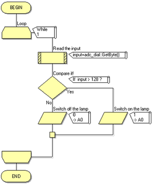
The flowchart will:
- Read the value set on the input device, the ADC dial.
- Compare this with a set value, and:
- if greater than the set value, turn on a lamp;
- if less, then make sure that the lamp is off.
- Loop back to the beginning, and repeat the process.
Create the 'input' variable
- In the 'Edit' menu, on the main toolbar, click on 'Variables...' to open the Variable Manager dialogue box.
- Hover just to the left of the 'Variables' label, and click on the down arrow that appears.
- Select 'Add new' and the 'Create a New Variable' dialogue box opens.
- Name the new variable "input".
- Leave the variable type as 'Byte'.
- Click on 'OK'.
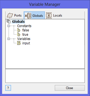
- The dialogue box is shown opposite.
Create the flowchart
- Inside the loop:
-
- Double click on it to open the dialogue box, so that you can configure it.
- The program 'knows' which components you have added to the System or Dashboard panel, and modifies the list of available commands accordingly.
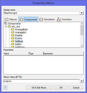
- Under 'Components', the ADC dial will be listed, and underneath it the list of commands.
- Scroll down the list and click on the 'GetByte' command.
- This reads the output of the analogue input device - the ADC dial in this case, and stores it in the byte variable called 'input'.
- Rename the 'Display name' as "Read the input".
- Click on 'OK'.
- Again, the dialogue box is shown opposite.
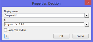
- Rename it "Compare it !"
- In the condition 'If' box, type "input>128".
- The '128' is totally arbitrary in this program. A byte variable can store any value from 0 to 255, so 128 is roughly half way.
- In this case, the program decides whether the value stored in the variable 'input' is greater or smaller than 128, and reacts differently depending on that decision.
- Click on 'OK'.
- Again, the resulting dialogue box is shown opposite.
- Double click on it to open the dialogue box.
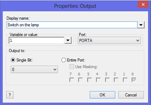
- Change the 'Display name:' to "Switch on the lamp".
- In the 'Variable or value:' box, type "1".
- Configure the rest of the box to output this to 'PORT A' 'Single Bit:' 0.
- Click on 'OK'.
- In the 'No' branch, drag and drop a second 'Output' icon.
- Double click on it to open the dialogue box.
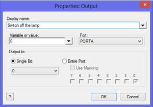
- Change the 'Display name:' to "Switch off the lamp".
- In the 'Variable or value:' box, type "0".
- Configure the rest of the box to output this to 'PORT A' 'Single Bit:' 0.
- Click on 'OK'.
- Again, the dialogue boxes for the 'Output' icons are shown opposite.
The flowchart should now resemble the one shown below.
Add the LED
- Locate an LED such as the LED 5mm Panel in the 'Outputs' toolbox in the Icons toolbar.
- Hover over the image to the left of the component label 'LED 5mm Panel', and click on the down-arrow that appears.
- Click on the 'Add to system panel' option to select it.
- Select the LED on the System panel and drag it to a suitable position.
- Look at the Panel Properties, the 'Connection' property make sure that it is connected to Port A, bit 0 ($PORTA.0).
- Leave it like this.
Add the ADC dial
The ADC dial represents a number of input devices.
- Locate the 'ADC dial' in the 'Inputs' toolbox in the Icons toolbar.
- Hover over the image to the left of the label, and click on the down-arrow that appears.
- Click on the 'Add to system panel' option to select it.
- Select the ADC dial on the System panel and drag it to a suitable position.
- Look at the Panel Properties, and locate the 'Connection' property. Just below it, the 'Channel' property shows that, by default, it is connected to 'AN0' - the first bit of the microcontroller capable of accepting an analogue input. Click on 'AN0' to open a pinout of the microcontroller.
- Click on the rectangle representing input 'AN1' to change the connection to this channel.
- Leave it like this.
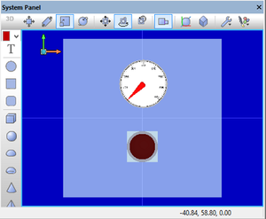
The System Panel should resemble the image shown at the top of the page.
Final testing
- Save the flowchart as 'Analogue,fcf'.
- Click on the simulation button
 .
. - Use the mouse to turn the pointer on the ADC dial, and notice what happens when you pass the half-way mark.
- Click on the 'Stop simulation' button,
 when you are happy with the program's behavior.
Download the exercise
You can download the file created by this exercise and open it in Flowcode to identify errors in your program/file or you could also download the file to skip to the next exercise.
- To download the file, click on the link below and then either:
- Click on the file name.
- Right click the file name and select 'Save link as...' or 'Save target as...' (depending on your browser).
