Phase Locked Loop (PLL)
A lot of the devices have an inbuilt PLL or phase locked loop which can be used to provide a variable frequency from a fixed source oscillator such as a crystal.
A common use for the PLL is to take the input crystal frequency and multiply this up to give a much higher clock frequency on board the device.
Some devices can even use their PLL with the internal oscillator allowing for maximum flexibility with minimal external parts.
The device datasheet should detail if a PLL is available to the device.
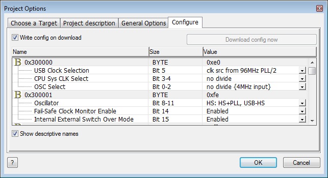
Some devices are very easy to configure and expose all the settings for the PLL via the configuration options. An example of this is the PIC18F2455 family which features a PLL to provide the functionality of boosting the input clock speed to 48MHz which is compatible with full speed USB communications. Here we have specified a 4MHz input clock speed and configured the oscillator to use the PLL multiplied version of the HS (HighSpeed) oscillator.
Some devices are not this simple and require a section of C code at the start of the program. These devices normally have to startup in a low speed mode and then switch to the high speed mode to allow the PLL to be configured correctly. The upside to these types of device is you can normally re-configure the PLL at any time to reduce power consumption etc.
Here is a piece of example C code used to enable the PLL on-board a PIC18F24J50 device.
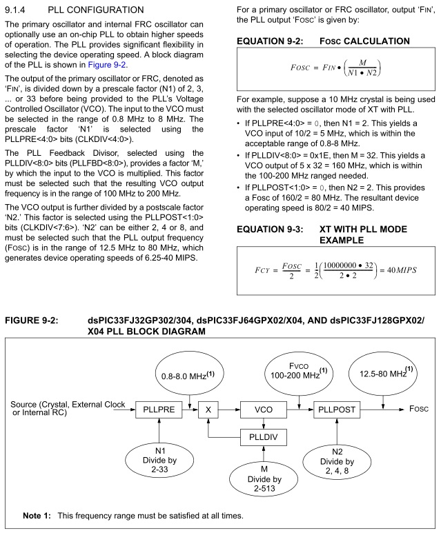
Here is an example of a much more complicated PLL where there is a large calculation using several parameters that determines the overall output frequency as seen on the dsPIC33FJ128GP802.
This takes the input clock speed of 12MHz and multiplies it up to 80MHz to provide the maximum clock frequency for the device which equates to 40MIPs.
Here is the PLL calculation plus information shown in the dsPIC33FJ128GP802 device datasheet.


