Exercise - Dashboard and System Panel - Controlling Multiple Objects
<sidebar>Sidebar: Flowcode Exercises:Ex2</sidebar> This exercise shows how to add two more LEDs to the car's instrument panel, each controlled separately by switches on the Dashboard Panel. These will warn the driver that the sidelights are switched on, and that a seatbelt is not fastened.
Contents
Open the 'Headlight warning' flowchart
- Open the flowchart 'Headlight warning' which you created in Exercise - Dashboard Panel - Adding Objects.
- This uses one switch, labeled 'main', operating an orange LED on the instrument panel.
Add the LEDs
- Add two more 'Single LEDs to the System Panel.
- Do this either from the 'Outputs' toolbox, as you did for the first LED, or by 'copying and pasting' that LED.

- In either case,
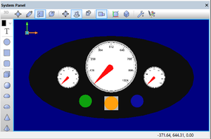
- give one coordinates 'X'= -60, 'Y'=-55, 'Z'=-1.75, and color it green;
- give the other coordinates 'X'= 60, 'Y'=-55, 'Z'=-1.75, and color it blue.
- All three LEDs should have the same size ('Wi...' =32, 'He...'=32, 'De...'=10).
- The System Panel now resembles the one shown opposite.
Connect the LEDs
The original LED is connected to PORT A, bit 1.
- Click on the each of the added LEDs in turn, and use the Panel Properties to connect:
- the left-hand LED (green) to PORT A, bit 0,
- the right-hand (blue) LED to PORT A, bit 2.
Add the switches

- Add two more 'Toggle Metal Panel' switches to the Dashboard Panel.
- As above, you can do this either from the 'Inputs' panel or by 'copying and pasting' the first switch.
- In either case, give one coordinates 'X'= 30, 'Y'=5, 'Z'=-2, and the other coordinates 'X'= 60, 'Y'=5, 'Z'=-2.
- All three switches should have the same size ('Wi...' =2, 'He...'=2, 'De...'=1).
- Create two further labels, either by dragging them onto the Dashboard panel, using the 'T' icon, or by copying and pasting the 'side' label.
- In either case, rename one "side", and give it coordinates 'X'=30, 'Y'=-15, 'Z'=0.5.
- Rename the other "belt" and give it coordinates 'X'=60, 'Y'=-15, 'Z'=0.5.
- All three labels should be the same size, ('Wi...' =10, 'He...'=10, 'De...'=2).
- The Dashboard Panel now resembles the one shown opposite.
Connect the switches
The original 'main' switch is attached to PORT B, bit 0.
- Connect the switch above the 'side' label to PORT B, bit 1, and the one above the 'belt' label to PORTB,2.
Binary arithmetic
Before creating the Flowcode program, here is a little background in binary arithmetic. The switches don't have to be read as separate items. Instead, they can be used to control the first three bits of a binary number applied to PORT B. The table shows the input binary number resulting from different combinations of switch presses:
| belt bit 2 |
main bit 1 |
side bit 0 |
binary no. |
decimal no. |
|---|---|---|---|---|
| 0 | 0 | 0 | 000 | 0 |
| 0 | 0 | 1 | 001 | 1 |
| 0 | 1 | 0 | 010 | 2 |
| 0 | 1 | 1 | 011 | 3 |
| 1 | 0 | 0 | 100 | 4 |
| 1 | 0 | 1 | 101 | 5 |
| 1 | 1 | 0 | 110 | 6 |
| 1 | 1 | 1 | 111 | 7 |
The way this works:
- The 'belt' switch is worth '4' in decimal, because it controls the third binary digit, and so is worth 22 (=4).
- The 'main' switch is worth '2' in decimal, because it controls the second binary digit, and so is worth 21 (=2).
- The 'side' switch is worth '1' in decimal, because it controls the first binary digit, and so is worth 20 (=1).
When more than one switch is pressed, the number generated, (whether in binary or decimal,)is equal to the sum of these values. So, when the 'belt' switch and the 'side' switch are both pressed, the number produced is '5'.
The Flowcode program senses this number using the 'Switch' icon.
Creating the Flowcode flowchart
- Modify the 'Headlight warning' program as follows:
- Double-click on the 'Input' icon to open the dialogue box.
- Change the 'Input from:' setting from 'Single Bit:' to 'Entire Port:'.
- Click on 'OK'.
- (The program now reads all devices connected to PORT B, and so inputs the number generated by the three switches.)

- Click on the 'Decision' icon, to select it, and then delete it (by pressing on the 'Delete' key, for example.)
- Drag and drop a 'Switch' icon to replace it.
- Double-click on it to open the dialogue box, and then:
- Rename it "Input".
- Insert the variable name "input" in the box following the label 'Switch:'.
- There are eight possible combinations of switches, giving input numbers up to 111 (7 in decimal), so click to add ticks to the boxes from 1 to 7.
- The dialogue box resembles the one shown opposite.
- Click on 'OK'.
- In the default branch, add an 'Output' icon, and double-click on it to configure it to output value 0 to the entire PORT A. Rename it "Switch off".
- In the '=1' branch, add an 'Output' icon, and double-click on it to configure it to output value 1 to the entire PORT A. Rename it "Switch on".
- This branch is activated when the 'side'light switch, alone, is pressed. The green warning light will come on as a result.
- In the '=2' branch, add an 'Output' icon, and configure it to output value 2 to the entire PORT A. Rename it "Switch on".
- This branch is activated when the 'main' switch, alone, is pressed. The orange warning light will come on.
- In the '=3' branch, add an 'Output' icon, and configure it to output value 3 to the entire PORT A. Again, rename it "Switch on".
- This branch is activated when both the 'side'light and 'main' switches are pressed. Both the green and orange warning lights will come.
- In the '=4' branch, add an 'Output' icon, and configure it to output value 4 to the entire PORT A. Rename it "Switch on".
- Follow this with a 'Delay' icon, configured to give a delay of one second.
- Then add a second 'Output' icon, configured to output value 0 to the entire PORT A, to switch the warning light off.
- Then add a second 'Delay' icon, also configured to give a delay of one second.
- This branch is activated when the 'belt' switch, alone, is pressed (because the seat belt is not in use.) The blue warning light flashes on an off repeatedly.
- In the '=5' branch, add an 'Output' icon, and configure it to output value 5 to the entire PORT A. Rename it "Switch on".
- Follow this with a 'Delay' icon, configured to give a delay of one second.
- Then add a second 'Output' icon, configured to output value 1 to the entire PORT A.
- Then add a second 'Delay' icon, also configured to give a delay of one second.
- This branch is activated when the 'side' and 'belt' switches are both activated. The program keeps the green warning light on, but makes the blue warning light flash on an off.
- In the '=6' branch, add an 'Output' icon, and configure it to output value 6 to the entire PORT A. Rename it "Switch on".
- Follow this with a 'Delay' icon, configured to give a delay of one second.
- Then add a second 'Output' icon, configured to output value 2 to the entire PORT A.
- Then add a second 'Delay' icon, also configured to give a delay of one second.
- This branch is activated when the 'main' and 'belt' switches are both activated. The program keeps the orange warning light on, but makes the blue warning light flash on an off.
- In the '=7' branch, add an 'Output' icon, and configure it to output value 7 to the entire PORT A. Rename it "Switch on".
- Follow this with a 'Delay' icon, configured to give a delay of one second.
- Then add a second 'Output' icon, configured to output value 3 to the entire PORT A.
- Then add a second 'Delay' icon, also configured to give a delay of one second.
- This branch is activated when all three switches are activated. The program keeps the green and orange warning lights on, but makes the blue warning light flash on an off.
The flowchart looks like the one below:

- Simulate the program to check that it responds correctly when different combinations of the switches are pressed.
- Congratulations! You have completed the construction of the car instrument panel.