Usage Cases
Contents
On this page we set out our vision for who uses, or will use, Flowcode, how they will use it and where the product is heading.
Differences between version 7 and previous versions
A bigger range of components
The usefulness of a design tool, to an engineer, is closely linked to the range of parts that can be incorporated into the design. Flowcode includes component creation software for users to create their own designs: electrical, mechanical and systems. By making it possible to create components we hope that the number of parts available in Flowcode will expand rapidly and the product will become more and more useful. There are already lots of components in Flowcode that are hidden from view on startup that we are using to test the capabilities of Flowcode. (open the Search filter and enter ‘all’ to see them)
Simulation
Flowcode has superb simulation capabilities. The great thing about simulation is that it allows you to test your design on-screen before you deploy it. This saves time. Simulation also allows you to set scenarios for your project to test it under more conditions than you find on the bench. So simulation also allows you to increase the chance of your design being successful once it is in the field. Simulation also allows you to understand your design better and is a great learning tool.
Test built in
Electronic systems engineers design tend to do one of two things:
- Control an electronic system
- Monitor an electronic system
Flowcode version 5, and earlier, allows engineers to develop programs to control an electronic system. That’s great. But what is much more useful is to develop software to control a system and to also measure the system’s performance so that you are 100% sure that it is doing what it is supposed to. Flowcode has loads of features that facilitate this.
Mechanical and 3D support
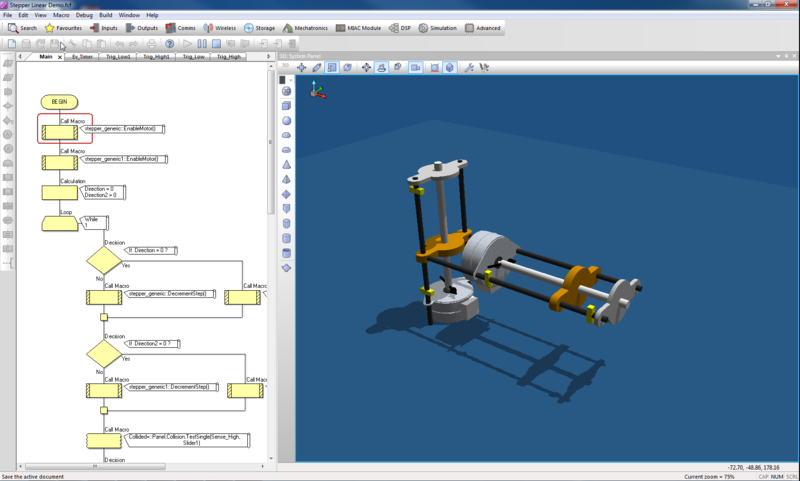
Engineers don’t design code, microcontrollers, or circuit boards. They design a system which makes use of code, microcontrollers, or circuit boards. With Flowcode we want to channel an engineer’s energy into thinking about the system; not into developing code for it. Flowcode now includes full 3D support and a range of API calls that allow engineers to work at a systems level. We are just getting started here. Take a look at some of the Example files to get an idea of what is now possible. We can now simulate complete mechanical systems like plotters and 3D printers: not just the mechanical drive systems but also the file decoding systems. The 3D engine and API calls facilitate other types of design and simulation: from heating water in tanks using PID algorithms to robotics. This is very exciting. 3D design files for electromechanical parts are now freely available and can be easily imported into Flowcode and used in engineer’s designs.
Our customer groups
When thinking about customers, what they need, and what features to put into Flowcode we classify three types of use:
- Those working at a circuit level
- Those working at an electromechanical level
- Those working at a systems level
Those working at a circuit level
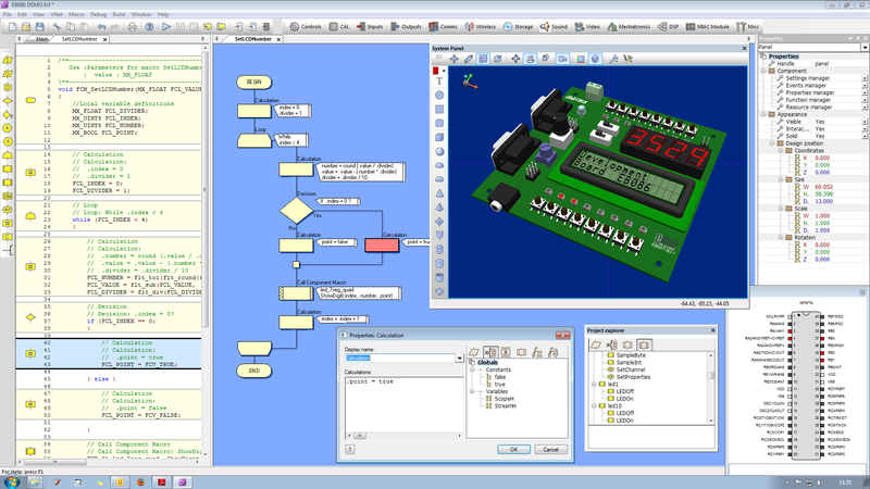
This is essentially what version 5 of Flowcode provided. These engineers have divorced their design from the system they are working on and are able to work at a circuit level to realise their design. They want to see the user components like switches, LEDs, LCDs, and are very familiar with electronics at a circuit level.
Those working at an electromechanical level
New in Flowcode. There are few mechanical designs that do not incorporate electronics. Many engineers working at a circuit level also want to connect that circuit to the mechanics, but do so ‘live’ on the equipment they are designing: and endless cycle of design, download, test. We want to provide resources for these engineers to be able to import their mechanical designs, to characterise their movement in Flowcode, to simulate the entire design and to develop not just the software that drives the machine, but also that decodes user files to drive the machine and connect it to the wider world.
Those working at a systems level
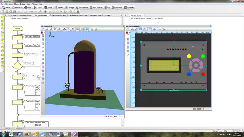
New in Flowcode. When working at a systems level the electronics design is a trivial task compared to the design of the overall system. If you consider the task of controlling the heat in a tank for example: the electronic circuit is relatively simple consisting of a heater unit and a thermistor. But predicting and managing the rate of temperature rise, the temperature hysteresis in due to sensor and heater lag, the damping in the system and other factors are where the challenges lie. Flowcode allows users to model the system under control, and to design an algorithm to control it. The fundamental control code will probably be easy. The mathematics behind it might not be. Working at a systems level is a real challenge for engineers and Flowcode provides real benefits for those who want to model their system.
Some examples of our customers and how they can use Flowcode
In this section we focus on some customer groups and explain why we believe they should use Flowcode.
Embedded Engineers
Embedded engineers generally have good working knowledge of circuits and software and traditionally use a C or BASIC compiler for developing microcontroller programs. Quite right too. Engineers at Matrix use C and C++ for most development work. But there are some times when you don’t need the efficiency or flexibility of C, and there are some times when just working with a microcontroller compiler/IDE alone is too limiting. That’s where Flowcode comes in handy as a way of getting projects up and running quickly, and verifying system performance. With Flowcode the justification here is stronger: simulation and test features are all designed to shorten design cycles, and Flowcode is surprisingly efficient in terms of code generation and execution speed. The close linkage of Flowcode to E-blocks and the open source nature of E-blocks circuit design, means that we offer an incredibly short time to design completion. Don’t be fooled into thinking that because Flowcode is based on flow charts it is somehow inferior to C. Just about all the constructs and features and functions you would find in a C compiler/IDE are available in Flowcode: but Flowcode is easier to use.
Test Engineers
Test engineers face a huge variety of challenges: from testing a new piece of circuitry another engineer has designed, through to stress testing the mechanics of a push bike to make sure it has been built up to standard. Test engineers can easily create simple microcontroller controlled boards for test application.
Test is at the heart of the architecture of Flowcode and our plans for making the product even more useful. Flowcode can now interface to third party test gear using DLLs and Flowcode can be used in a SCADA-like mode on a PC to facilitate this. At the time of writing we already have a Velleman 8055 USB input output card component within Flowcode and a basic Picoscope oscilloscope component with hardware macro calls users can easily call as part of their test routine. In fact any third party instrument with a DLL supplied can be called through a SIMulation macro. The MIAC USB Slave component allows a MIAC PLC to be connected and controlled via the Flowcode simulation for switching in signals or loads as part of a test rig. We are working closely with instrument manufacturer TTI to provide power supplies and signal generators which will have control components in Flowcode.
Mechanical Engineers
There are few mechanical systems without electronic control systems. To date mechanical engineers needed to work with an Embedded engineer to realise a system: they don’t have the time to become expert programmers. But as Flowcode is syntax independent with a low learning curve mechanical engineers can use Flowcode to develop control systems themselves.
Flowcode has many new features for Mechanical engineers with the new 3D graphics engine. Importing STEP, IGES, STL files from programs like Solidworks is straightforward. For the first time mechanical engineers can develop the mechanics of a product at the same time as the electronic control parts and see their designs working on-screen.
Chemical Engineers
Chemical and process control engineers can now model the systems they are designing inside Flowcode. They can start with a 3D model of the system, can characterise the model and its behaviour, and they can then design the control program for it on-screen. They can deploy the design on a microcontroller, a MIAC or on a PC. Or any one of the three for different projects of variants of the project.
Other Engineers
Engineers need to pull all of the various aspects of a system together into one place so that all the different technologies in the system interact and work together seamlessly. The Flowcode simulation environment is a great place for performing this task as it allows engineers to link in real world hardware and provide graphical representation of what is going on: through simulation, in circuit test, and deployment on a wide variety of targets. The range of engineers using Flowcode is wide: from Automotive to Sports Science.
Education / Learning to program
Flowcode started life as an educational piece of software to make embedded technology more accessible for students. There are currently more than 1,500 educational institutions using Flowcode: from 12 year old students in Belgium learning about the basics of robotics, through to undergraduate engineering students in France developing novel electric vehicles.
Flowcode is an ideal programming language for education as it provides a very straightforward interface to programming and gets around common mistakes such as syntax problems and typos. Flowcode has a low learning curve: all students can understand flow charts. But Flowcode is well featured so that students can start with simple systems and go on to develop complicated ones. Flowcode is usable by a wide range of educational disciplines.
The other surprising thing about Flowcode is that it facilitates learning at a systems level where data structures and protocols are important and code details are not. For example: students can learn about the Bluetooth and internet protocols, can see the layering of information in these protocols and can practice coding techniques in designs with many microcontrollers without getting bogged down in coding syntax.


