MIAC RC5 Remote Control
 The RC5 communications protocol developed by Philips is one that is in common use and is available as an option in most programmable handsets. This article will explain RC5 and by using the versatile MIAC device and the Flowcode programming language; show how you can use this protocol for your own projects.
Introduction
RC5 is a communications protocol developed by Philips for infra-red remote control. It is in common use with many domestic appliances, and is available as an option in most programmable handsets.
Transmission is relatively slow. Each bit has a typical period of 1778µs – with large variations tolerated. A standard RC5 transmission contains 14 bits (nearly 25ms per message). There are tables of default devices and functions associated with the information transmitted.
A typical breakdown is:
- 2 start bits.
- 1 toggle bit – new button press or auto repeat.
- 5 address bits – device type (TV, VCR, etc.).
- 6 data bits.
Coding
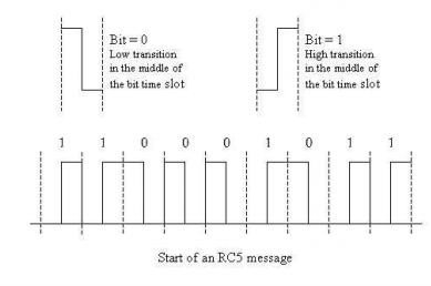
RC5 is transmitted using Manchester coding. Each bit is represented by a transition in the middle of its time slot. This guarantees that there will be at least one transition associated with each bit, which helps to maintain timing synchronisation in the receiver. The relative values of the preceding and succeeding bits determine whether there is a transition at the start or end of the bit time slot.
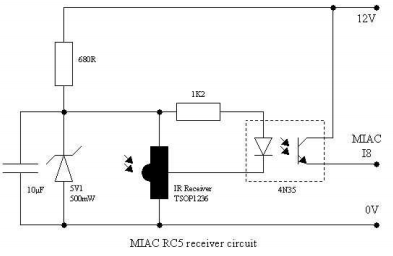
Receiver circuit
For transmission, these pulses are modulated by a 36KHz square wave carrier with a 25% duty cycle. The receiver used for the example circuit is one of a range of devices that perform several functions, including demodulation of the signal. The output of the receiver is the original Manchester coded pulse stream. The output of the receiver is a 5V inverted signal. This needs to be considered when connecting directly to a microcontroller. The example circuit re-inverts the signal as it conditions it for the MIAC 12V input.
The RC5 system has been designed to be tolerant of significant timing variations. This was a requirement for early handsets with inaccurate oscillators and batteries operating over their full charge range.
Decoding
The two start bits (bit = 1) are always present in RC5 transmissions. They can be used to synchronise the receiver timer at the start of each message, so that each data bit can be sampled at the appropriate time. This is similar to the bit-banging approach often used with software RS232 receivers.
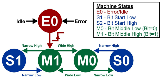
An alternative method, possible with Manchester coding, is to measure the time between successive transitions. A Manchester coded message consists of a combination of 4 pulse types:
- Wide high
- Narrow high
- Wide low
- Narrow low
These definitions can have large timing tolerances applied to them before there is confusion between short and long pulses; removing the need to know the exact transmission frequency, and allowing decoded using software based on a state machine.
Example program
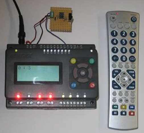
The example program linked to this article runs on a MIAC and uses the I8 (INT2) input to detect transitions in the receiver signal.
The program can be easily adapted to run on other target devices. It was originally developed for a PIC16F84A running at 4MHz, and has been imported into Flowcode for AVR and run on ATmega324P with a 20MHz crystal. The only modifications required are the timer management instructions, calculations based on the clock frequency, interrupt control, and signal polarity.
The interrupt service routine runs the state machine, and manages the TMR0 timer and INT2 edge selection.
Any timing faults or illegal combinations of transitions are detected and cause the state machine to reset to its start condition.
When a full sequence of 14 bits has been successfully received, the address (including the toggle bit) and the data value are made available to the main program as two byte variables. A flag is set to indicate the presence of a new pair of values.
This simple program uses the numeric keys ( 1 to 8 ) of the remote keypad to toggle the states of the eight corresponding MIAC outputs.
The received address and data are displayed on the LCD. Information from keys not used for this application can also be displayed so that they can be included in programs performing other functions. The function of the toggle bit can also be seen (bit 5, value 32, in the address byte)
Some commonly used addresses are:
- TV = 0
- VCR = 5
- SAT = 8
The main program can be modified so that individual units only respond to messages with specific addresses.
A range of multi-function programmable handsets have been tested with this project. All worked successfully when programmed with one of the Philips TV codes. If the handset has device options (VCR, DVD, AUX, etc) it might be possible to find codes that produce similar key data, but at different addresses.
The example code created for this blog article can be viewed here.
7,773 total views, 3 views today


