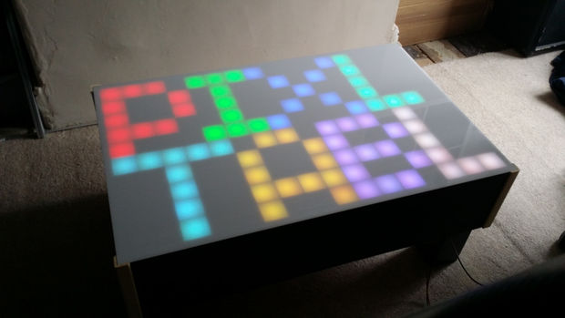
RGB LED Pixel Touch Reactive Gaming Table
Tables are useful items to have and as we needed a new coffee table for the lounge it made sense to build my own with a few extra electronic features.
My table design consists of the following features.
- 10 x 16 RGB LED array
- 10 x 16 IR touch sensor array
- SD card storage
- Audio output with volume control
- Bluetooth connectivity
Here is a list of the table’s current capabilities, the games are all one or two player with AI control for the 1 player games which require 2 players.
- Tetris
- Pong
- Tic Tac Toe
- Snake
- Countdown Timer
- Calming Animation
- Game of life
- Touch Visualizations
Step 1: The Design


Most designs similar to this seem to use multiplexing. Now multiplexing is very good and I have used it to great effect on my LED cube and POV display projects but with this design I wanted to try something a bit different. It’s initially a bit more work but I’m hoping to save on the hours of wiring all the LEDs and IR sensors and receivers later on.
I decided instead to create a chain of intelligent microcontroller nodes. Each node has a single RGB LED, an IR emitter and an IR detector and that’s about it. Each node communicates using the UART (Universal Asynchronous Receiver Transmitter) serial peripheral on-board the microcontroller.
Doing things this way means that my master controller can focus on complex tasks like streaming audio or playing a game while the slave nodes handle the menial tasks like controlling the LED colour and filtering the IR readings for touches. It also means the design is fairly scale-able allowing you to create tables containing any number of pixels.
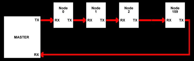
The master is connected to the nodes using it’s own UART peripheral. The transmit signal of the master is connected to the receive signal of the first node. The transmit signal of the first node is connected to the receive signal of the second node and so on. The master communicates with the slave nodes by sending out a series of command bytes. Each node listens out for the command bytes and as they are received the node has a possibility to react to or modify the byte before sending it back out to the next node and eventually back to the master.
Step 2: Bill of materials
Here is the bill of materials I used in my table. I would suggest you read through the guide first a few times before ordering any bits or committing to a design so you don’t make the same mistakes I made.
The Nodes x 160
1 x Node PCB – Eurocircuits
1 x RGB LED – Farnell 2401106
1 x PIC16F1823 – Farnell 16F1823-I/SL
1 x IR Emitter – Farnell 2290428
1 x IR Receiver – Farnell 2290430
1 x Quality Servo Motor Extension Cable – eBay
2 x 10R 0603 Resistors – Farnell
1 x 68R 0603 Resistor – Farnell
1 x 82R 0603 Resistor – Farnell
1 x 47K 0603 Resistor – Farnell
The Master Electronics x 1
1 x 3V3 3A/5A DC PSU – eBay
1 x EB091 DSPIC Ghost Programmer – MatrixTSL
1 x EB037 Card Reader – MatrixTSL
1 x EB086 DSP Audio Output – MatrixTSL
1 x EB002 Screw Terminals – MatrixTSL
1 x EB084 Graphical LCD (Debugging Only) – MatrixTSL
1 x HC06 Bluetooth Module – eBay
1 x Good Quality SD card – Amazon
6 x Length of low gauge power rail wire – Farnell
7 x Length of medium gauge comms wire – Farnell
1 x 3V3 5A DC Supply – eBay
The Table Hardware x 1
2 x Spruce Side Panel – 850mm x 200mm x 18mm – B&Q
2 x Spruce Side Panel – 567mm x 200mm x 18mm – B&Q
9 x Laser Cut Sections – 850mm x 50mm x 3mm
15 x Laser Cut Sections – 531mm x 50mm x 3mm
2 x MDF Sheets – 850mm x 531mm x 6mm – B&Q
4 x Pine Corner Angle – 203mm x 25mm x 25mm – B&Q
1 x Milky White Acylic Sheet WH10 – 886mm x 567mm x 3mm – Modulor.de
1 x Decking Post – B&Q
1 x Black Wood Stain – B&Q
Step 3: The Node Circuitry


The node circuit is pretty basic using the cheapest PIC microcontroller I could find with enough I/O to allow me to drive the various on-board components.
The RGB LED is a common anode type LED so the corresponding LED channel is lit by pulling the cathode pin low by the microcontroller. Each channel has a current limiting resistor allowing the max LED current to be fixed at just under 20mA. The LED colour is set by toggling the LED channel cathode pins on and off at high speed. The longer the LED is on, the brighter the colour becomes allowing for a very wide range of colours to be displayed.
The IR emitter is also connected directly to an output pin of the microcontroller. This time driving the pin high will light the IR LED. Again we use a current limiting resistor to fix the IR LED current to around 20mA.
The IR detector is biased to ground using a resistor and the signal from the detector is fed back to an analogue input pin on the microcontroller.
Shown in the images is the schematic and PCB layouts for the nodes. The PCB layout was made as small as possible as PCB costs from my local manufacturer (Eurocircuits) are generally based primarily on board size and quantity ordered.
Also attached below are the Gerber files sent to the manufacturer to produce the node PCBs. I also ordered a top layer surface mount solder paste stencil as part of the order to make the assembly stages a bit easier.
Step 4: The Node Firmware

The Node Firmware was created using the Flowcode software. I designed the functionality using the standard macros and then once the design was complete and working I used my USBee protocol analyser to improve the efficiency of the firmware by taking out some of the unnecessary elements of the Flowcode macros. The ability to embed C code directly into the Flowcode code means you can really squeeze every drop of processor run time out of the micro.
Attached is the node firmware and the serial UART data protocol detailed in an libre office and excel document.
Following is a brief description of the macros used in the node fimware Flowcode project.
Main – Called on reset, contains our initialisation code and the main program loop.
Tmr0 – Called automatically on a 15.625KHz timer interrupt to allow us to clock out the RGB LED colour and to take the IR readings.
UartRx – Called automatically when a byte is received on the serial UART, deals with processing the bytes and generating appropriate responses.
Step 5: Testing Nodes

I ordered enough nodes to allow me to create two complete tables but initially only built six nodes by hand. I wanted to be able to effectively test the nodes and tweak the values before building the entire batch and potentially getting something fundamental wrong.
I’m glad I did this because there were some initial problems mainly to do with the IR.
The IR emitter receiver pair I am using is low cost and very small but probably not ideal. The IR output seems a little weak and both sunlight and shadows interfere with the IR feedback somewhat so you get mixed results at different times of the day. To try and make the best of this I hooked up my scope to the IR enable and IR detect signals so I could see exactly what was going on.
One thing I could have done is give the IR emitter more current to try and make the output brighter. However I didn’t add a transistor to the IR emitter circuitry on my PCB design so I have to live with the 20mA provided by the PIC microcontroller. A transistor would just be yet another component to fit by hand 160/320 times per table anyway.
My first trick was to fit each of my six nodes with a different bias resistor for the IR detector. I tested the readings with no touch, light touch and full hands on touch at various times of the day and recorded the values. I also created a routine where the master controller recorded each node’s minimum and maximum readings and left the circuitry on for several days to collect data. From my readings the bias resistor of 47K was providing the most stable readings across the board.
My next trick was that the light from the RGB LED was also triggering a response from the IR receiver. So to get around this problem my node firmware only outputs to the LED for half the time. The other half of the time the RGB LED is switched off to allow the IR to be sampled in as clean as possible state. This repeats at high speed so you don’t see the flicker of the LED switching on and off.
Finally I added a software low pass filter to the IR readings so that when the IR is enabled it constantly takes new readings and maintains a filtered version of the current reading. This then helps immensely to collect a fairly stable and reliable reading.
The touch readings range from Red (0-15) which is a light touch through to green (16-31) and then to blue (32+) which is a heavy touch.
I have found for the IR to work reliably you need a good two or three point light source. If you have this then the IR will react very well. If the ambient light is low then the IR sensors will start to pick up noise.
Step 6: Mass Producing Nodes


Next came producing the nodes in large quantities. Rather than soldering each PCB by hand I opted to bake the surface mount components using a standard reflow process. Note that if you do this then don’t use your home oven, the gas released off the solder paste is fairly toxic and you don’t want it being baked into your food. I simply use a toaster oven I bought off eBay for £10 to bake all my boards.
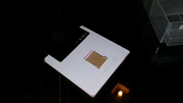
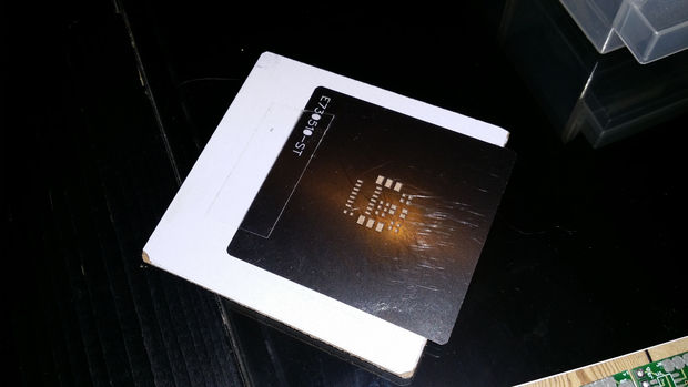
The first step was to create a jig to put the solder paste onto the PCBs. I used my trusty CNC machine and routed a pocket the size of the node PCB with an additional small slot to allow me to remove the PCB from the pocket. I then placed a PCB in position and lined up my solder paste mask over the surface mount pads. Using some tape I secured the paste mask in position and this creates a hinge to allow me to add or remove the PCB in between applying paste.
Next I worked in small batches of 15 – 40 boards at a time. I would put each board in turn into my jig and apply solder paste to the surface mount pads. Next using my pair of tweezers I carefully placed each component into it’s position on the PCB and pressed down gently into the solder paste. Once all the components were on I gave each board a quick check to ensure I hadn’t missed anything and then the boards went straight into the oven to be baked. I could do about 20-30 nodes in an hour by hand but with a proper surface mount pick and place machine you could go a lot faster.
My initial plan was to try and save some time by connecting each node together using servo extension cables I bought from eBay. However the SIL headers tended to move about a bit during reflow meaning their connectivity was less than ideal. Also don’t try using copper clad board as a support in the oven as I did, it just warps in the oven and creates a nasty stink. A ceramic tile or similar would be much better. In the end I simply left the SIL headers off and soldered the connections by hand after baking and this gave me much better results.
Step 7: Connecting Nodes Together


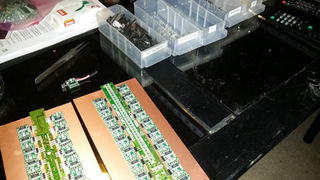
I now had a big pile of node PCBs all waiting to be tested and linked together.
After a bit of trial and error with joining nodes together using servo extension cables as mentioned in the last section I decided to try a different approach.
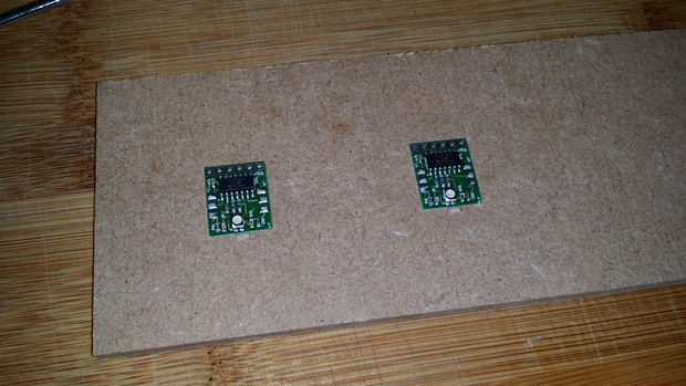
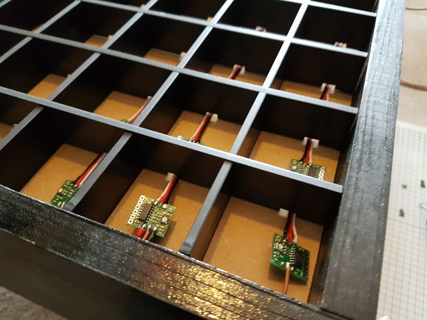
I again got out my trusty CNC machine and routed out two pockets the size of the node PCB into a piece of MDF. Each pocket was the correct space apart to maintain the pixel pitch required to suit my table dimensions. Two PCBs were placed in the pockets and a section of the servo expansion cable was soldered in between.
The last image highlights the difference between my first approach and my second approach using a jig. I think here the lesson is “always use a jig”.
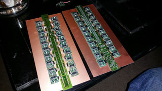
I went through all my nodes connecting them together in sets of 16. Then using a slightly longer piece of 3-core ribbon wire I connected the sets of 16 together to make sets of 32 or two full columns of pixels on the table.
Once this was done I added longer lengths of individual wire to the two end nodes so that they were ready for testing and then eventually wiring together.
To test the ribbons I completed the node firmware and then loaded each node with the program using my PICkit 3 programming tool. To connect the PICkit 3 to each node I placed a 6-way SIL header into the socket on the PICkit and then placed the other end into the socket on the PCB. When programming you simply have to hold the PICkit in a way where you are gently forcing the connection on all 6 pins. You do this by keeping the node PCB flat on the table and leaning the PICkit slightly in either direction.
Once the firmware was loaded onto each node in the chain I programmed the master with some code to address the nodes, light them all up as red, green and blue in order and then to show the value of their IR on their RGB LED. This allows me to check all the functionality much quicker then testing a board at a time. I built and baked a total of 320 nodes and in the end I only had two nodes fail during the testing, one of which was quickly fixed with my soldering iron. Not bad going considering.
Step 8: Frame & Partition Walls
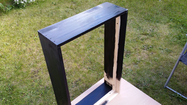
The frame was made using spruce furniture board which was cut to size, drilled, sanded, screwed together and sanded again before applying a dark stain and varnish.
There is a internal baton on three sides of the frame which acts to hold the display base and house the inner electronic workings. This has to be placed at the right height to allow the base MDF to sit on top and the partition walls to sit on top of that and be flush with the top of the frame. The baton needs to be wide enough so all your electronics will fit within it’s dimension.
For the partition walls I started by using my table saw to create strips of MDF at the right height. After sawing all the strips to the right size I stacked them all up together and noticed that they were anything but straight. I then changed my plans and drew up the partitions in SketchUp ready to be laser cut. Even the laser cutter seemed to give me some problems in terms of straightness but it’s far better then my initial wooden attempt.
I placed notches in the laser cut designs to allow the node interconnecting cables to run between compartments. I offset the notches in a way to allow the RGB LED to always be in the center of each compartment. I’m glad I did this as you can really tell when the LED is not centralized.
I had two pieces of MDF cut to size to form the top and bottom of the electronics compartment. In one piece I marked 10 holes along the narrow side to allow me to run the node column wires through to the controller.
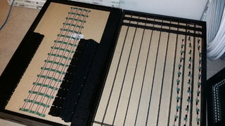
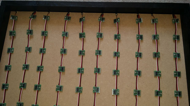
I laid out all the sections of 32 nodes in place on the top of the electronics compartment and then started sliding the partition walls into place. Once all the walls were in place I started to manipulate the cables on the nodes to get them all to sit as flat as possible with their LED in the center of the compartment. Some of the outer nodes had to be glued into position but I tried to keep the glue as minimal as possible so the nodes could be removed and serviced in future if anything goes wrong.
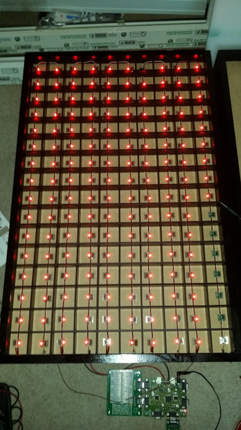
The last image shows the testing of the first complete table. The last row has a few nodes missing so I can immediately spot where the problem might be. In this case the node was functional but the UART hardware seemed damaged so I swapped out the node for a freshly made one.
Step 9: Wiring Together

Wiring together is fairly simple. I just lifted the frame up onto it’s side and the gives you great access to the electronics compartment. Later this will be covered by the second piece of MDF to protect all the electronics.
I started by gathering all the power and ground wires together, twisting the wires together, creating a hook and then attaching a single wire to the hook before flowing solder into the join and covering with heatshrink. The communications wires are daisy chained together so you end up with two wires from either end of the table. These are your transmit and receive signals.
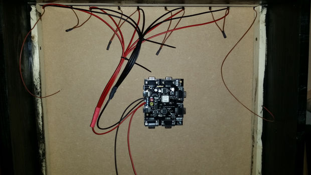
Step 10: The Brain
With the frame still on it’s side it’s now time to start thinking about what your application controller is going to consist of. You could use such things as a Raspberry Pi or an Arduino however I decided to go for the EB091 from MatrixTSL which provides a 16-bit PIC complete with DSP hardware and running at a rate of 70 million instructions per second (MIPs). Raspberry Pi was tempting but I didn’t want to get bogged down in the world of Linux again just yet.
To my EB091 I added the following functionality by simply bolting on E-blocks boards. These can be a bit pricey as they are meant for lab work and rapid prototyping but each one has the full schematic laid out in the datasheet should you wish to replicate the circuitry on your own custom PCBs.
- SD Card – EB037 Card Reader
- Transmit/Receive UART connections – EB002 Screw Terminals
- Audio Output – EB086 DSP Output
- Bluetooth – EB024 Bluetooth
The EB091 also had some functionality that makes it very handy for this type of application. Such as large RAM buffers for audio streaming, holding pixel colours and IR values. Also lots of peripherals, 4 UARTs, 4 SPI, 16 PWM etc. And finally it has some nice debugging features as part of the Flowcode / Ghost interface so I can use it to monitor whats going on as it’s running.
Once I was happy with all the electronics I used a sheet of thin MDF cut to size to cover and protect all the inner workings. I then attached the wooden feet using angled brackets to hold the MDF in place. Finally any nodes that were not quite sitting flat I glued down into position using a hot glue gun.
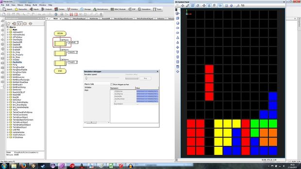
Step 11: Software – Simulating the Table
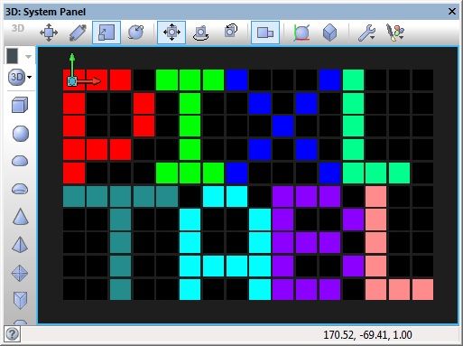

To speed up the development of the firmware I created a simple way of simulating the RGB LEDs and IR interaction using the Flowcode software itself.
The LEDs are created using panel primitive objects and coloured to match to contents of the RAM array during the RAMWrite macro.
The IR interaction is done by creating an event macro to detect mouse clicks on our panel objects.
The simulation can even stream the game audio though I haven’t found a nice way to make it repeat just yet.
A video of the simulation being used to play a game of Tetris is available here,
https://www.youtube.com/watch?v=xPaWR79AeEU
You can even play the game if you like. You just need a copy of Flowcode 6 installed on your computer (the free demo version will do) and then download and open the attached Flowcode file and click the play button.
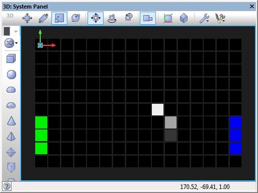
Step 12: Software – Main Menu
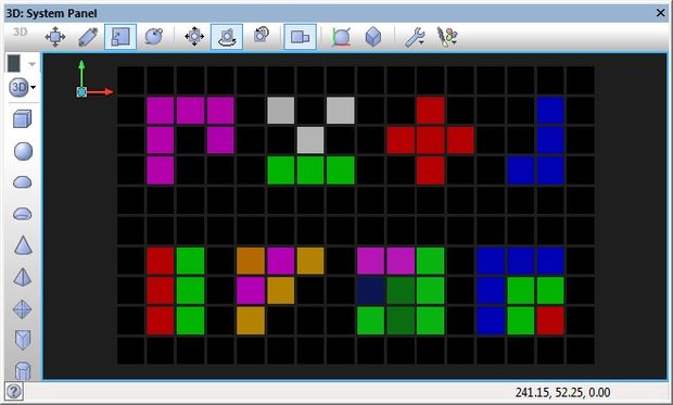
The main menu is the way of browsing around the various functions of the table and will appear shortly after the initial table test routine. From the menu the user can select what function they want the table to perform.
As we don’t have a massive amount of pixels I created a simple icon for each of the functions I wanted to add to my table. Each icon sits within a 5 x 4 pixel box allowing 8 menu items. I chose my menu items to represent the following:
Snake, Pong, TicTacToe, Tetris
Mine Sweeper, Count Down Animation, Game Of Life Animation, IR Feedback Visualisation
Step 13: Software – Streaming Audio
Streaming audio is a task in itself. I want to be able to play some music and sound effects to go along with the games so to do this requires a software routine to allow me to open a file on the SD card and then output that file a sample at a time to my DSP audio output board.
We can do the audio output without the DSP board by simply using a PWM channel on the microcontroller at a high frequency to output the signal. I originally used PWM as the output but then I got hold of the EB086 DSP Audio Output Board and compared the quality when using the on-board DAC and the sound quality is significantly better than the PWM alone. The DSP board also provides me a variable filter, a loud speaker and adjustable amplifier so I don’t have to bother with these items.
The first thing I did was to create my music tracks. I went and found music that went with the game in question and created a medley of all the tracks using the free software Audacity. I then saved the file onto the SD card as a 16KHz 16-bit WAV file.
It’s then simply a case of opening the file in software and reading out the file into a buffer. The output is then driven using a timer interrupt to pull samples out the buffer and send them to the DAC or PWM on a regular 16KHz tick. As the buffer is fairly small (20KB in my firmware) we have to be sure to re-fill the buffer every so often to keep the audio streaming. Once we reach the end of the audio file there is a short pause and then the file is re-opened to begin streaming again from the beginning.
To control the volume of the audio I cut the volume control potentiometer off the EB086 board and then wired in a new potentiometer with wires long enough to reach the edge of the case. The pot is then mounted to the case so it can be easily adjusted.
Here are the functions used for audio processing.
WAVStartStream – Used to set the name of the WAV file on the card to stream and starts the streaming process by filling the buffer and starting the timer running.
WAVFillBuffer – Called periodically to maintain a steady supply of bytes in the sound buffer. Buffer can take about 0.4 seconds worth of samples @ 16K samples per second.
WAVStreamInterrupt – Called automatically at 16KHz by the timer peripheral on the microcontroller device.
WAVStopStream – Stops the audio stream and clears the sound buffer.
Step 14: Software – Tetris
For anyone who wasn’t born in the 1980s. Tetris is a simple game where various objects of 4 pixels scroll onto the screen one at a time. You can move the objects left and right as well as rotate and drop down to the bottom.
The aim of the game is to stack the blocks nicely so you get complete rows. When you get a complete row the row disappears freeing up the game area for more objects. The game is over when no more objects can be fit onto the game area. As the game proceeds the objects move faster and faster making efficient stack harder and harder.
The two player mode comes in two flavors where you can play in coop or vs modes.
In coop mode each player controls half of the gaming area and each player manipulate their own objects on their side of the game area. A completed line most run through both sides of the gaming area to be removed from play. The game is over when either player can no longer legally place an object on the gaming area.
In vs mode a completed line must only run through the players half of the gaming area. The game is over when a player can no longer legally place an object on the gaming area.
At the end of the game the number of complete rows made is shown before returning to the menu.
Following is a brief explanation of the macros used to create the Tetris game.
Tetris – Main game macro containing the code to play the game.
TetrisCheckForFullLines – Checks for any complete rows, if any are found then they are removed with a simple animation and everything above them is shifted down.
TetrisCoordinates – Generates the four coordinates for the current new shape and handles rotations.
TetrisDrawObject – Draws or removes the current new shape on the display.
TetrisIsObjectOnScreen – Used to determine end game if the object is not fully on the screen when moving to the next object.
TetrisMoveObject – Used to shift the object down the display and to handle user input. If the object collides with another item then the object is moved back and the function flags that the move failed.
TetrisPickNextObject – Used to randomly select the next object to appear.
TetrisReadInput – Used to poll the IR sensors on the table and find the user input based on maximum touch reading.
Step 15: Software – Pong
For anyone who wasn’t born in the 1970s. Pong is a simplified form of table hockey where you cannot move the paddles away from the edge of the table. As the game continues the ball speed increases making the game harder and harder. A point is won if the ball makes it past the paddle to the edge of the table.
The game is finished when a player reaches a score of 5 goals.
Following is a brief explanation of the macros used to create the Pong game.
Pong – Main game macro containing the code to play the game.
PongAI – Allows for AI based control over a paddle for 1 player and 0 player modes.
PongDrawBall – Draws the ball on the table.
PongDrawPaddle – Draws the player paddles on the table.
PongInput – Reads the IR sensors and controls the paddle positions.
Step 16: Software – TicTacToe

TicTacToe or Noughts and Crosses here in the UK is a simple game where each player takes it in turn to make a move by selecting one of nine squares to place their marker. The game is won by having a row of three matching markers either horizontal, vertical or diagonal.
Following is a brief explanation of the macros used to create the TicTacToe game.
TicTac – Main game macro containing the code to play the game.
Step 17: Software – Game Of Life
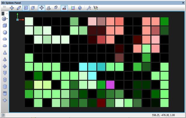
Game of life is a cellular automation by John Horton Conway. It is a zero player games which uses rules to simulate the behavior of organic cells.
I have adapted the game to my own rules mainly to make it my own but also to try and create an entertaining visualisation which can be run on the table.
Each cell starts off with a random value of the following specifics. Food, Water, Resources and Radiation and is represented by a single pixel on the table.
Both food and water are required for life to be sustained and multiply. As the cell’s population increase the food and water supply will start to dwindle. Resources are required to attempt to move from one cell to another. Radiation builds up over time as the population increases and can mutate or kill off the population.
Food, Water and Resources build up over time if the cell is empty of life and the radiation levels gradually go down.
A random seed life form in one or more cells is used to start the game and the game then runs from there.
The lifeforms are shown by the colour of the pixel on the table, the intensity of the colour indicates the population.
Following is a brief explanation of the macros used to create the game of life visualisation.
GameOfLife – Hosts the game’s main loop with a loop to go through and process the entire table cell by cell.
GOLCellControl – Allows the cells population to be controlled easily and randomly without worrying about overflows and colour alterations.
GOLParamControl – Allows the various cell parameters (Food, Water, Resource, Radiation) to be altered easily and randomly without worrying about overflows.
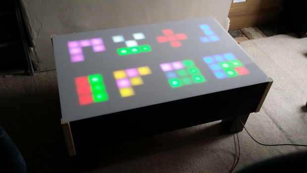
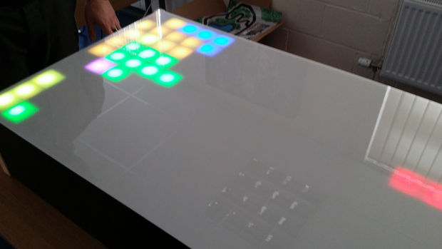
Step 18: The Finished Design

Here is a look at the finished design with some photo’s of my workmates enjoying themselves.
Here we have a video of some of the elements at work,
The master node software is still a work in progress and is likely to keep evolving. As I have a USB cable hanging out the bottom of my table I can connect up my laptop whenever the need arises and update the firmware.
On my To Do list is the Snake game, better pong control and some more good animations. An auto mode would be nice to for when you just want it as an animated table.
The latest source can be found here.
23,233 total views, 3 views today
Related Posts


About The Author
BenR
Embedded engineer with experience in Cybernetics (HMI), Robotics, Mechatronics, Control Systems and Communications using Microcontrollers and Microprocessors.
That is so awesome.
You need to make a kit for this. You could sell many of them.
Bob