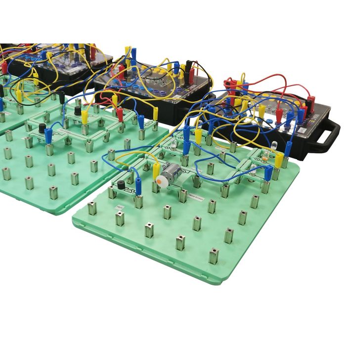
CAN and LIN Bus V3
Key Features
- A complete solution to learning
- Includes worksheets with teacher's notes
- ANSI version available
- Includes MIAC NXT
This kit consists of 6 MIAC NXT educational Electronic Control Units and accompanying Locktronics boards which
mimic the electrical system in a vehicle.
The system includes 3 CAN bus networks at different speeds: CAN
convenience bus, CAN drive train bus, CAN OBDII bus and a LIN bus for the instrument cluster. One MIAC NXT
performs the function of a Gateway ECU which provides communication between the system and OBDII scan
tools.
The 6 Locktronic / MIAC nodes are:
A - Body and control front
B - Engine control
C - Instrument control
D - Powertrain control
E - Body control – rear
F - Gateway and master
The CAN and LIN bus system can be enhanced through the addition of real automotive sensors and actuators
that are added to the system.
Software
Software included allows a Windows PC to connect to the hardware and show the communications flowing through the various busses on the software. It emulates a simple dashboard and includes decoded readouts for various sensors and actuators in the system.
Selecting each of the decoded readouts will highlight corresponding bus and message showing where the data is coming from. Also available is a console view with optional filter that provides an time based log of the incoming messages. Messages can be overwritten or injected into the running system.
Curriculum
Accompanying free curriculum is provided for Level 3 students (CAN and LIN BUS fundamentals) and level 4/5
students (CAN bus: Under the hood). The system makes use of the J1939 open CAN bus standard and the J1979
OBDII standard so that it is compatible with all third party scan tools. A PC based diagnostic program provides
a graphical display of the functionality of the system and allows students to see the CAN/LIN/OBDII messages
on the buses.
2 curriculum are available with this kit:
CAN AND LIN BUS FUNDAMENTALS CP0607
This course gives an introduction to the use of CAN buses and LIN buses in automotive applications. It is a
practical course designed to teach students the basics of CAN and LIN bus connections and voltages, and it
also teaches students how to debug faults in CAN and LIN systems.
The course makes use of the Matrix CAN bus system: this consists of 6 educational Electronic Control Units
and accompanying Locktronics boards which mimic the electrical system in a vehicle. The system includes 3
CAN bus networks at different speeds, a LIN bus and a Gateway ECU which provides communication between
the system and OBDII scan tools.
The CAN and LIN bus system can be enhanced through the addition of real automotive sensors that are
added to the system.
Learning objectives:
- CAN and LIN bus wiring
- ECU function
- Network topology
- CAN and LIN bus
- Using scan tools
- Debugging CAN bus systems with a multimeter
- Circuit design for fault detection
CAN BUS UNDER THE HOOD CP0411
The first of our automotive network courses - CAN and LIN bus fundamentals - gives an introduction to CAN
and LIN networks in vehicles and how to use multimeters, oscilloscopes and OBDII scan tools to diagnose
faults. This course takes the student a step further into CAN and LIN bus protocols and explains how they
are used to pass information between the ECUs in a vehicle. The course also gives an insight into how vehicle
designers construct a system of ECUs and circuits to provide the functionality that modern vehicles require.
The course makes use of the Matrix CAN bus system: this consists of 6 educational Electronic Control Units
and accompanying Locktronics boards which mimic the electrical system in a vehicle. The system includes 3
CAN bus networks at different speeds, a LIN bus and a Gateway ECU which provides communication between
the system and OBDII scan tools.
The CAN and LIN bus system can be enhanced through the addition of real automotive sensors that are
added to the system. See our Automotive sensors product.
Learning objectives:
• PC based diagnostics
• Sensors and actuators in CAN andLIN bus systems
• CAN bus message encoding
• LIN bus message encoding
• ECU and vehicle circuit function
• Gateway function: CAN to LIN, LIN to CAN
• Start up routines
• J1939 CAN bus protoco
• OBDII functions


